23
Flow Chart
Gladiator Conductivity Switch Series
Diagnostic Displays (Remote type only)
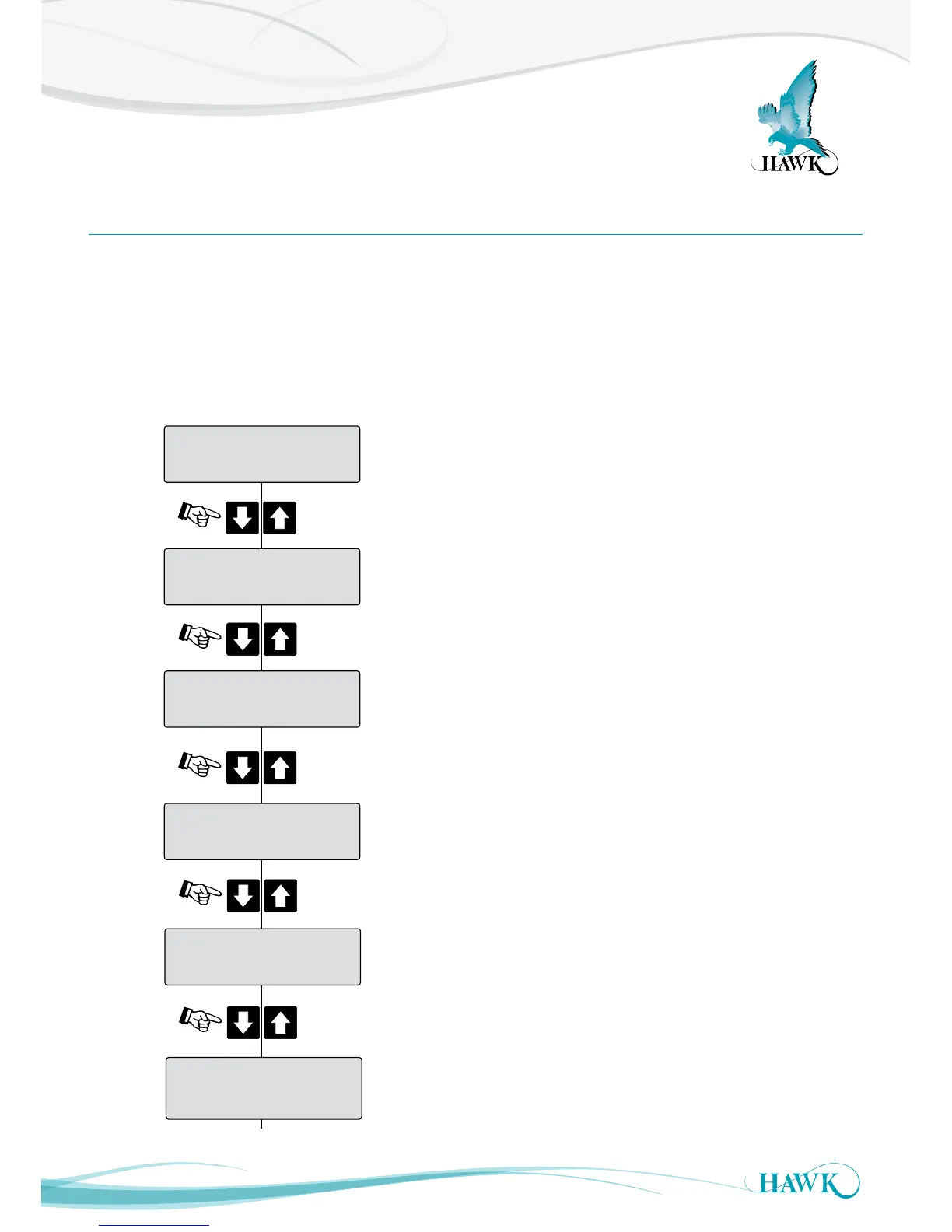
The diagnostic displays appear on the top line of the LCD, after pressing the Up or Down push button when
the Gladiator switch is in its normal running mode.
The diagnostics provide the user with valuable performance feedback on how the instrument is performing
whilst in operation.
The measured reading Sensor Value (%) continues to be displayed on the second line of the LCD during
diagnostic viewing on the top line. Ouput relays will continue to operate during diagnostic viewing.
Normal
0.0%
Press
Press
Press
Min: 0.0%
0.0%
Press
Operation Mode
Current temperature inside probe housing (ºCelsius).
Programmed switch On / switch Off delay (seconds).
Minimum captured Sensor Value % since last history
log reset, or last Cal Mounting operation.
Normal / Comms Retry / Fail
Maximum captured Sensor Value % since last
history log reset, or last Cal Mounting operation.
Press