8
Wiring
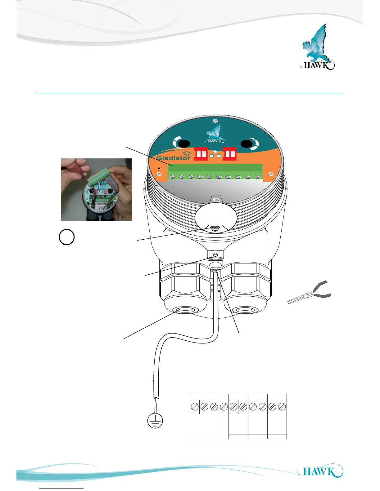
Gladiator Conductivity Switch Series
Smart Probe
1 2 3 4 5 6 7 8 9 10
S
E
N
S
I
T
I
V
I
T
Y
D
E
L
A
Y
HI
FSH TESTCAL
1. NC
RELAY
2. COM
3. NO
COMMS DC-IN AC-IN
4. Test
12-30Vdc
80-265Vac
+
7.
8.
N
9.
L1
10.
RS 485
5.
B
6.
A
-
GLADIATOR SMART PROBE TERMINAL LAYOUT
Hole for securing of
optional identification tag
M4 grounding screw
Ground the housing to
vessel, if vessel is metallic.
Ground the housing to
plant ground, if vessel is
non-metallic.
The AC earth/ground
cable must be connected
to the ground screw
inside the housing when
using AC power.
If only one cable is used for both
power and output signal, then the
second entry port must be
plugged or blinded. Every Smart
unit is supplied with two M20
glands (or 3/4”NPT adaptors)
mounted on the unit and one
blind plug loose.
Remove Plug-In terminal
block for easier wiring.