6
Mounting
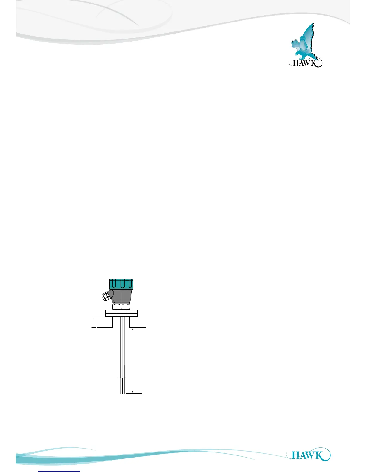
Gladiator Conductivity Switch Series
Probes can be mounted from the top,
side and bottom.
Points to consider when mounting:
A. Material Infeed Clearance
Install the probe away from the infeed to minimize the
influence of build-up and impact forces, and to avoid
false triggering from product flow.
B. Wall Clearance
Install the probe far enough away from the vessel wall
to prevent the probe from coming into contact with the
wall and prevent conductive build-up from bridging
the probe to the wall over time. Avoid creating a
confined area where material could build-up.
See note
C. Nozzle Clearance
Ensure the probe does not come in contact with the
mounting nozzle.
D. Top mounting
When top mounting, ensure adequate clearance is
provided between probe and wall. Avoid creating a
confined area where material could build-up over
time.
See note
E. Side mounting
It is highly recommended to install any side mounted
probe at a downward angle of 30-45º. Use a
protection plate for side mounting where the probe
may be subject to impact damage.
F. Bottom mounting
Bottom mounting is not recommended. Only mount
from the bottom if no build-up of material occurs. If
low level mounting is required, suitable options are
shown in the diagram on next page.
INCORRECT MOUNTING NOTES:
(Refer to diagram on next page)
Incorrect mounting because the probe is too close
to the wall or roof. Positioning too close to a wall or
roof may allow material build-up between the probe
and the vessel.
Incorrect mounting because the probe is touching
the nozzle. The probe must not touch the nozzle or
any part of the vessel. Conductive build-up must
not bridge from the probe to the nozzle or reference
probe.
Recommended 50mm (2”)