10 USE ONLY GENUINE REPLACEMENT PARTS
INSTALLATION:
This manual contains instructions for installation, operation, maintenance, troubleshooting, and parts lists for the proper operation of
the swimming pool/spa/hot tub heaters. It is strongly recommended that the installer read the manual before installing the
swimming pool/spa/hot tub heater. If after reviewing the manual any questions remain unanswered, contact tech services or local
representative. Following heater installation, the installer should leave all manuals with the consumer for future reference.
NOTICE: The installation instructions are intended for the use of a qualified technician, specifically trained and experienced
in the installation of this type of heating equipment. Some states or provinces require that installer be licensed. If this is the
case in the state or province where heater is located, the contractor must be properly certified.
THE USE OF A POOL COVER IS RECOMMENDED. A pool cover reduces heat loss, conserves chemicals, lowers the
load on filter systems and may provide a valuable safety feature
EQUIPMENT INSPECTION: On receipt of the heater, inspect the heater carton(s) for damage. If any carton(s) is damaged,
note it when signing for it. Remove the heater from the carton(s) inspect it and advise the carrier of any damages at once.
NOTICE: Do not drop the heater from a pickup truck tailgate to the ground. This may damage the heater.
UNCRATING THE HEATER: Follow these steps to
remove the shipping carton from the heater:
1. Remove the corrugated carton from the heater. The
carton, top pad, bottom pad, and the four corner posts can
be recycled.
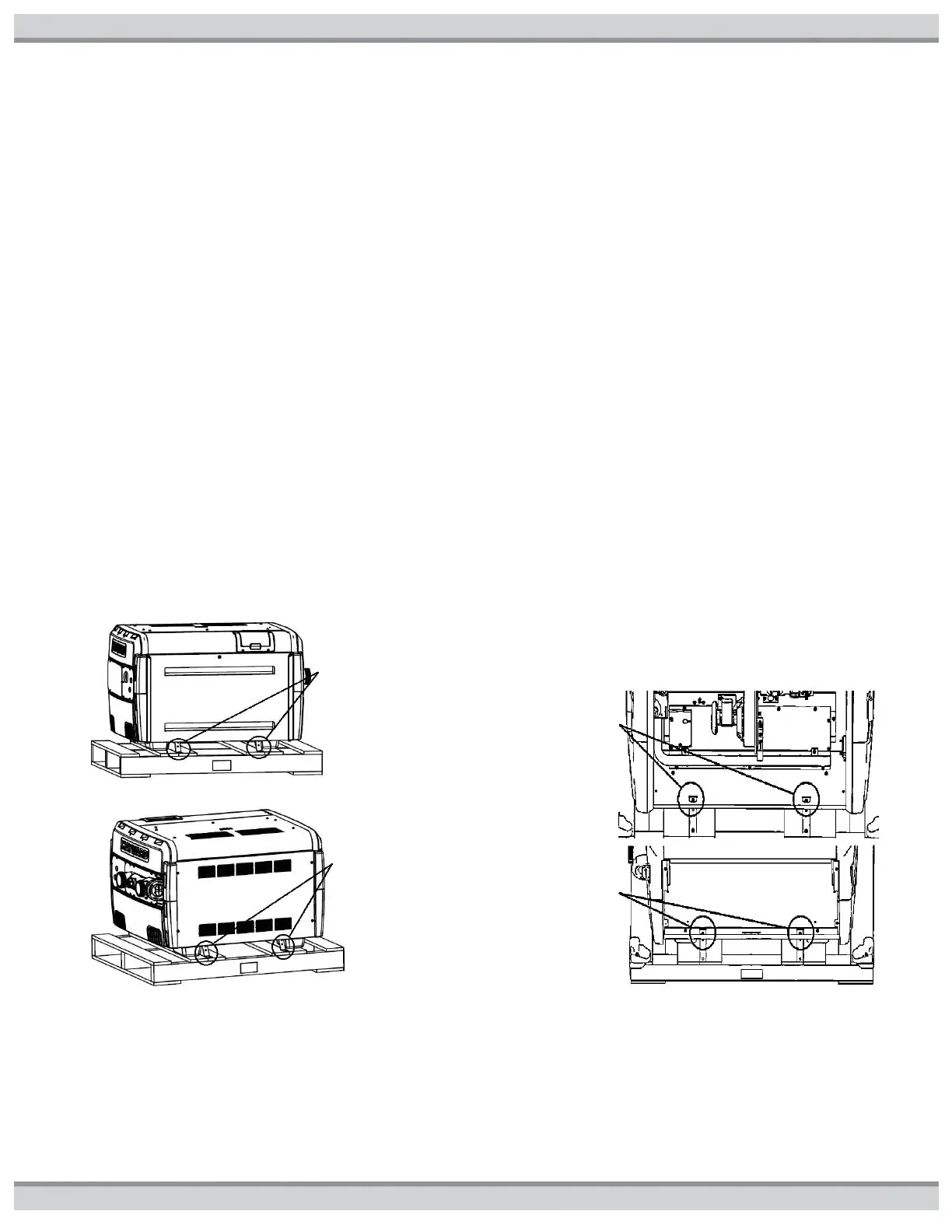
2. There are four (4) external screws (see figure3) used to
secure the heater to the wood pallet. All four must be
removed to separate the heater from the pallet.
Figure3: External Shipping Screw Locations
3. To access the four (4) internal screws (see figure4), open
the front access panel by removing the single top screw.
Then remove the two (2) screws and brackets which hold
the heater base pan to the pallet shown in Figure3. Next
open the rear access panel by removing the four (4)
screws holding this panel. Then remove the two (2)
screws and brackets which hold the heater base pan to
the pallet as shown in Figure3.
4. Lift the heater clear of the corrugated bottom pad and off
of the pallet. Discard bottom corrugated tray and pallet
appropriately.
Figure4: Internal Shipping Screw Locations
Front shipping
screws and
brackets
Rear shipping
screws and
brackets