26 USE ONLY GENUINE REPLACEMENT PARTS
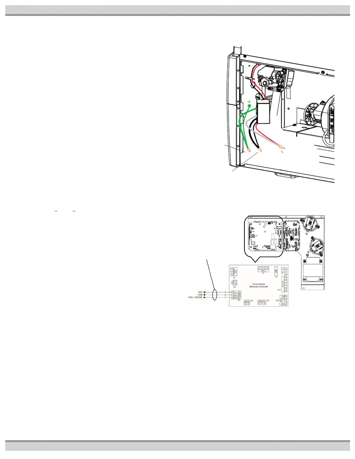
supplied caps. The power connections are to be made to the
supplied wires inside the junction box (see Figure22a) using
field supplied wire nuts. All connections are to be stored within
junction box attached to side panel.
REMOTE CONTROL CONNECTION: Remote control can be
accomplished via a 2-wire or 3-wire connection (see
Figure22b). The 2-wire connection allows thermostat control
where the remote temperature is sensed and calls for heat
when needed. The 3- wire remote switches function between
“POOL” and “SPA”. The set point temperatures for “POOL”
and “SPA” operation are still controlled locally. The 3-wire
remote simply provides a convenient way to manage the
“POOL” or “SPA” mode selection. Remote wiring is
accomplished using the factory supplied remote wire harness.
Remote wiring must be run in a separate conduit from power
supply. Use 22 AWG wire for runs less than 30 feet. Use 20
AWG wire for runs over 30 feet. The maximum allowable run is
200 feet.
2-WIRE REMOTE CONTROL CONNECTION: Connect the
appropriate wires from the remote control to the factory
harness ORANGE wire (“POOL”) and WHITE wire (“COM”). To
configure the heater for 2-wire remote thermostat control, use
the “MODE” key on the heater keypad to put the control into
“STANDBY” mode. Then simultaneously press and hold the “(
- )” and “MODE” keys for 3 seconds until the display shows the
code “bo” (bypass operation). Once in bypass operation, press
the ‘MODE’ button until ‘POOL’ or ‘SPA’ LED is illuminated.
The control is now ready to operate in 2-wire remote
thermostat control. The heater’s thermostat will only function
to limit the return water temperature to a maximum of 104°F.
3-WIRE REMOTE CONTROL CONNECTION: Connect the
appropriate wires from the remote control to the factory
harness ORANGE wire (“POOL”), WHITE wire (“COM”), and
RED wire (“SPA”). No control ‘MODE’ configuration setting is
needed, only connection of all three remote control wires. To
operate the heater with a remote 3-wire switch, the heater’s
control must be in “STANDBY” mode. The “STANDBY” LED
will be illuminated. When the remote switch is set to “Pool” the
“POOL” LED will be illuminated and the water temperature will
be displayed. When the remote switch is set to “Spa” the “SPA”
LED will be illuminated and the water temperature will be
displayed. The heater will use its internal thermostat to
regulate the water temperature to the set point of the mode
selected.
Figure22a: Junction Box Connections
Figure22b: Remote Control Connections
CHECK-OUT & START-UP:
GENERAL: The heater is equipped with a control system that automatically monitors the “Pool” and “Spa” temperature set points
and control devices. Then when heat is needed, turns on the combustion air blower, hot surface igniter and gas valve to light the
burners and monitor the flames. Figure23 provides a summary of heater components and their locations. Some of the following
procedures will require the heater to be operating. The Full lighting and shutdown instructions are included in this manual as well as
on the lighting and operating label affixed to the inside of the front access panel of the heater. Water must be flowing through the
heater during any operation. Check that the pump is operating and the system is filled with water and purged of all air prior to
starting the heater.
remote wire
 Loading...