USE ONLY GENUINE REPLACEMENT PARTS 11
SPRINKLER HEADS: The heater is designed to handle the wettest weather conditions that are typical of rain and high
humidity. Sprinkler heads force high-pressure water into the unit from the side at an odd angle. Make sure there are no sprinkler
heads near the heater that will spray on or into the unit. Many sprinkler systems are connected to a well system, whose water is
high in minerals, Sulphur, salt and other aggressive contaminates, that will leave a buildup on the unit and electronics causing
corrosion and shortens life.
NOTICE: Damage from sprinkler interaction is not covered under the warranty agreement. Make sure that sprinklers are
placed at a sufficient distance away so that normal wind will not carry the mist to the Heater.
NOTICE: If located in an oceanfront area, the Heater should be placed out of direct spray of sand and salt. This will clog,
damage, and corrode the unit. You may also consider protecting the unit by creating a physical barrier outside of the minimum
clearances between the unit and the prevailing beachfront wind. Damage caused by sand or salt spray is not covered by the
warranty.
LOCATING THE HEATER:
Locate the pool/spa heater in an area where leakage of the heat exchanger or connections will not result in damage to the area
adjacent to the heater or to the structure. When such locations cannot be avoided, it is recommended that a suitable drain pan, with
drain outlet, be installed under the heater. The pan must not restrict airflow. This heater must be installed at least (5) feet from the
inside wall of a pool (in-ground or above-ground)/spa/hot tub unless separated from the pool/spa/hot tub by a solid barrier. The
heater must be installed such that the location of the exhaust gas vent assembly outlet relative to adjacent public walkways,
adjacent buildings, openable windows, and building openings complies with the National Fuel Gas Code (ANSI Z223.1/NFPA 54)
and/or CAN/CGA B149 installation codes.
1. Level surface for proper rain water draining and removal.
2. Suitable electrical supply line. See rating plate on the heater for electrical specifications. A junction box is not needed at the
heater; connections are made inside the unit electrical compartment. Minimum wire size to be selected per NEC.
3. Electric disconnect switch that will interrupt all power to the unit. This switch MUST be within line of sight of the heater.
4. The heater does not require additional vent piping when installed outdoors.
5. Do not install in a location where growing shrubs may in time obstruct a heater’s combustion air and venting areas.
6. Do not install this appliance under an overhang less than 72in from the top of the appliance. The area under the overhang must
be open on (3) sides.
7. Do not install the heater where water spray from ground level can contact the heater. The water could reach the controls
causing electrical damage.
8. Do not install under a deck.
9. Do not install within 24in of any outdoor HVAC equipment.
10. Do not install where water may run-off a roof into the heater. A gutter may be needed to protect the heater.
CAUTION: Make sure the heater is not located where large amounts of water may run-off from the roof into the unit. Sharp
sloping roofs without gutters will allow massive amounts of rainwater, mixed with debris from the roof to be forced through the
unit. Failure to follow the instructions may result in property damage and void warranty.
11. Any enclosure around the heater must provide a combustion air vent large enough to accommodate input ratings of all gas
appliances in the enclosure. See AIR SUPPLY section for more detail
12. For minimum exhaust vent clearances for all building openings, including but not limited to vented eaves, doors, windows, or
gravity inlets, see Figure5. In Canada, the heater must be installed with the top of the vent at least 10 feet (3m) below, or
to either side of, any opening into a building.
OUTDOOR AND INDOOR INSTALLATION AND SERVICE
CLEARANCES: For both outdoors and indoors installations,
the installation clearances from combustible materials and
service clearances shown in Table3 and Figure5 must be
maintained. Do not install heater in a closet or enclosed space
(consult NFGC)
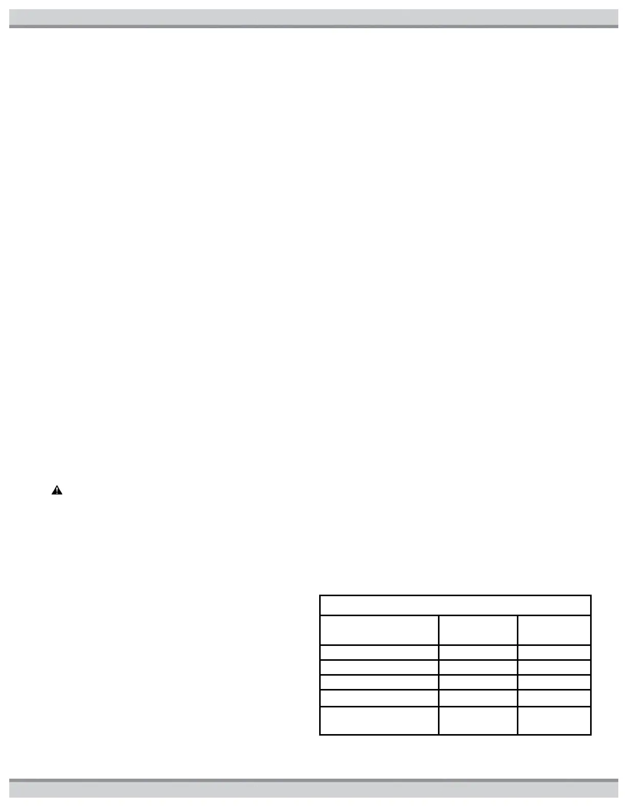
*If the heater is to be installed with vinyl siding at back,
increase the clearance in Table3 to 12 inches to avoid potential
discoloration of siding
Table3: Installation Required Clearances (in.)
Opposite Water Side
Connection

 Loading...