22 USE ONLY GENUINE REPLACEMENT PARTS
WATER PIPING:
REVERSIBLE WATER CONNECTIONS: This heater is designed so that it can be installed with the water connections located on
either the right or left side. Heaters are factory-shipped with right-side water connections. To move the connections to the left side
follow the instructions below and reference Figures1 and 14 as needed. A trained service technician must perform these steps
before the heater is installed.
1. Before beginning, be aware that it is not necessary to
remove the water header from the heat exchanger to
perform this manipulation. When this procedure is
complete, the water inlet will be located at the BACK of
the heater. The water outlet will be located at the FRONT.
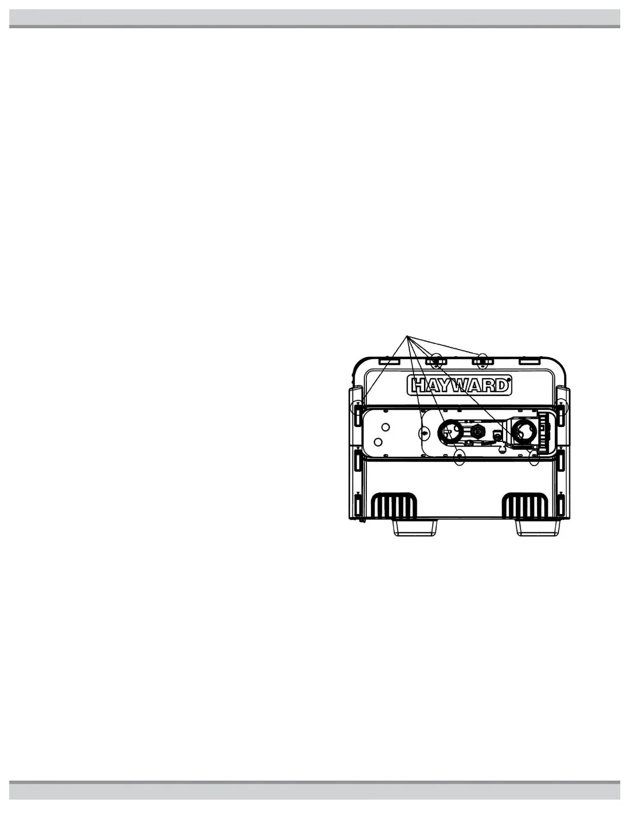
2. Remove screws and remove both of the upper plastic
heater side panels (see Figure14). Note the wires that
pass through a hole in the heater side panel go through a
split-bushing, which will allow separation of the wires from
the panel without disconnecting them.
3. Disconnect the 2 wires connecting the heater wire
harness to the heat exchanger header. One is located on
the water pressure switch and one is located on the
temperature limit switch, both on the top of the header.
Pull these wires into the heater cabinet from the hole in
the right- hand metal side panel in the heater, and re-
route them out through the left-hand metal side panel in
the heater.
4. Remove countersunk screws on the heater top and
remove louvered exhaust panel on heater top (see
Figure1).
5. Remove the heater top flue cover by removing 3 screws
on each side of the heater (see Figure1).
6. Remove screws and remove rain shield assembly (see
Figure1). Note that there are screws which hold the rain
shield assembly to the heat exchanger tube sheets, which
also must be removed.
7. Remove the front access panel (see Figure1).
8. Disconnect water temperature sensor plug from the
ignition control board located inside the heater (see
Figure1).
9. Pull the water temperature sensor wires out of the heater
cabinet through the hole in the right-hand metal side
panel.
10. Lift and rotate the heat exchanger 180 degrees. Do not
flip. Use care when setting the heat exchanger in place
do not damage the white sealing gaskets or combustion
chamber refractory.
11. Route the water temperature sensor wires into the
heater cabinet through the hole in the left-metal side
panel, and re-connect to the ignition control board.
12. Re-connect the heater wire harness to the water
pressure switch and temperature limit.
13. Reverse the above disassembly steps to reassemble the
heater.
Figure14: Screw Locations on Side of Unit
NOTICE: The heater is for use with pool and spa/hot tub water furnished by municipal water distribution systems only. Do not
use with mineral water, seawater (PPM>5000), or other non-poTable waters which invalidate the warranty. Do not install any
restriction in the water pipe between the heater outlet and the pool/spa with the exception of; three-way switching valve, in-line
chlorinator and/or chlorinator check valve.