USE ONLY GENUINE REPLACEMENT PARTS 25
DRAIN VALVE INSTALLATION (ASME MODELS ONLY): If
installing an ASME model heater, a 3/4” brass drain valve must be
installed. A drain valve is included separately with all ASME heaters.
Apply a suitable amount of pipe thread sealant or Teflon tape to the
threads and install as shown in Figure21.
PRESSURE RELIEF VALVE (ASME MODELS ONLY): If installing
an ASME model heater, a 3/4” pressure-relief valve having a
discharge capacity greater than or equal to the Btu/hr input of the
heater, and a pressure rating equal to or less than the working
pressure must be installed. See the rating plate located inside the
front access panel on the heater for the input rating and working
pressure. An appropriate pressure relief valve is included separately
with all ASME heaters. Apply appropriate pipe thread sealant or
Teflon tape to the threads and assemble as shown in Figure21.
Please note that the drain valve must be installed before the
pressure relief valve. Install the pressure relief valve with the
discharge connection facing the ground. If necessary, connect a
pipe (of the same size as the valve outlet) to the outlet and run it to a
code appropriate place of discharge. Do not install any shut-off or
restriction in this pressure relief discharge line.
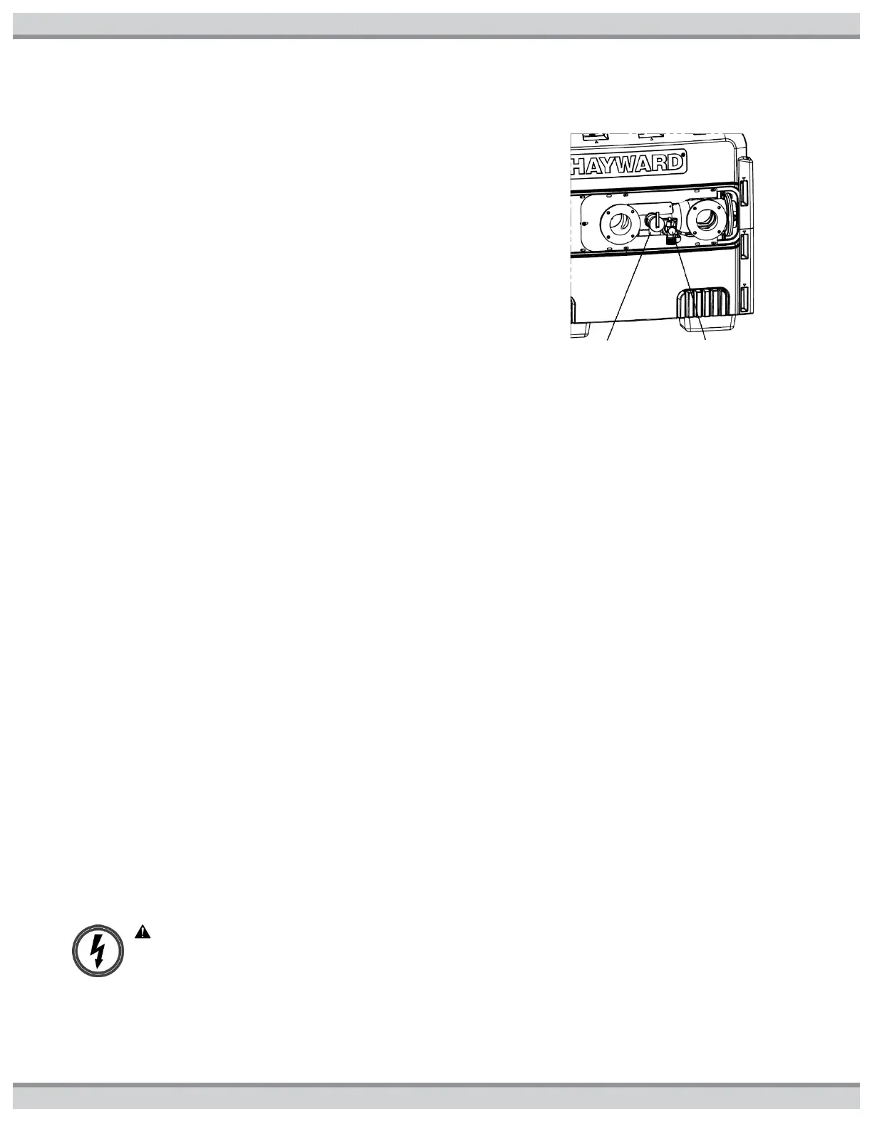
Figure21: Drain and relief valve locations
PRESSURE RELIEF VALVE (NON-ASME MODELS ONLY): Some local building codes require a pressure relief valve for non-
ASME pool/spa heaters. The plastic header has a 3/4” port which can be used for this purpose (see Figure21 for location of port). A
3/4” pressure relief valve having a discharge capacity greater than or equal to the Btu/hr input of the heater, and a pressure rating
equal to or less than the working pressure is recommended. See the rating plate located inside the front access panel on the heater
for the input rating and working pressure. If desired, you may order the pressure relief valve; order p/n CHXRLV1930. Remove the
factory-installed pipe plug, and install the pressure relief valve using an appropriate amount of pipe thread sealant or Teflon tape on
the threads. Install the pressure relief valve with the discharge connection facing the ground. If necessary, connect a pipe (of the
same size as the valve out- let) to the outlet and run it to a code appropriate place of discharge. Do not install any shutoff or
restriction in this pressure relief discharge line.
ELECTRICAL CONNECTIONS:
GENERAL INFORMATION: An external supply of power is required to operate the control system of the heater. The electrical
specifications for this heater are 120 or 240VAC, 60Hz, 1-phase, 5.5A maximum current. It is recommended that circuit protection
for the heater circuit be rated at 15 Amperes. The heater is shipped from the factory wired for use with 240VAC, 60 Hz field power
supply. To convert the heater to 120VAC, 60 Hz operation remove the 240VAC voltage selector jumper from the ignition control
board and replace it with the 120VAC jumper. These jumpers are tie-wrapped together and are located on the fuse board. See
Figure23 for location of the fuse board. All wiring connections to the heater must be made in accordance with the latest edition of
the National Electrical Code ANSI/NFPA 70, unless local code requirements specify otherwise. In Canada, follow CSA C22.1
Canadian Electrical Code, Part 1. The heater must be electrically grounded and bonded in accordance with local codes or, in the
absence of local codes, with National Electrical Code, ANSI/NFPA 70. Wiring connections must be made as shown in the wiring
diagram found inside the heater cabinet, and a copy is provided for convenience in the GETTING STARTED section at the
beginning of the manual. The heater must also have an independent ground and bond connection. There is a ground lug inside the
control box adjacent to the power connections per figure22 and a bonding lug on the side of the heater per figure13. Use a solid
copper conductor, size No. 8 AWG (8.4 mm2) solid copper bonding wire or larger for bonding conductor. Run a continuous wire
from external bonding lug to reinforcing rod or mesh. Connect to the grounding lug provided and to all metal parts of swimming pool
or spa, and to all electrical equipment, metal piping (except gas piping), and conduit within 5 ft. (1.5 m) of inside walls of swimming
pool or spa. IMPORTANT - Reference NEC codes for all wiring standards including, but not limited to, grounding, bonding and other
general wiring procedures.
WARNING: Risk of Electric Shock Review all safety information provided in the GETTING STARTED section of
this manual prior to servicing. Always disconnect power circuit before servicing. This heater contains wiring that
arries high voltage. Contact with these wires could result in death or personal injury.
ELECTRICAL CONNECTIONS: The heater may be
installed with the electrical service and optional remote control
wiring entering the heater cabinet on either the left side
junction box or right side using the floating junction box. There
are (4) openings for electrical entry. The junction box must be
used for field power wiring. Plug any unused openings with the
 Loading...