24 USE ONLY GENUINE REPLACEMENT PARTS
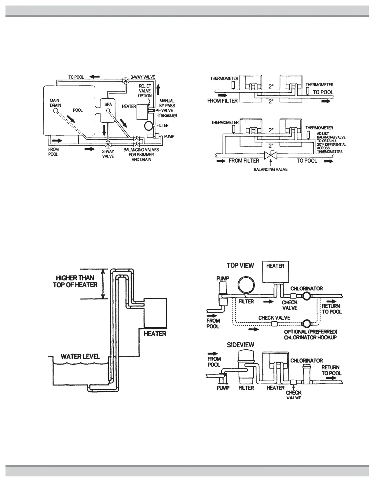
Figure17 illustrates a typical pool piping diagram and layout for the pool equipment. Figure18 illustrates a multiple heater installation
for very large pools with and without a manual bypass valve.
Figure17: Typical Plumbing to Pool or Spa
INSTALLATION ABOVE POOL/SPA SURFACE: If the
heater is installed less than three (3) feet above the surface
of the pool/spa water, install eyeball fittings or directional flow
fittings on the end of the return water line to the pool/spa to
create adequate back pressure at the heater to operate the
pressure safety switch when the pump is running. If the
heater is installed more than three (3) feet above the surface
of the pool/spa water, install a loop as shown in Figure19 to
prevent drainage of water in the heater during a filter change.
For installation above or below the pool/spa surface, refer to
START UP section for proper pressure switch setup.
Figure19:Installation Above Pool or Spa
Figure18: Multiple Heater System
AUTOMATIC CHLORINATORS AND CHEMICAL
FEEDERS: If used, a chlorinator must be installed
downstream from the heater in the pool return line and at a
lower elevation than the heater as shown in Figure20. Install
a separate positive seal corrosion resistant check valve
between the heater outlet and the chlorinator to prevent
highly concentrated sanitizer from back siphoning into the
heater. Back siphoning may occur when the pump is shut off
and a pressure differential is created.
Figure20: Automatic Chlorinator