14 USE ONLY GENUINE REPLACEMENT PARTS
High-Altitude Conversion Procedure:
1. Identify the altitude of the installation site. This may be done using a GPS device, or by looking up the altitude for the geographic
location. Altitudes for all locations in the United States and Canada may be found using the zip/postal code database at
www.zip-codes.com. If the altitude for the installation site is greater than 10,100 ft., the heater may not be installed. Note that if
installing outdoors, some heaters may be compatible with your altitude without modification. Table4 lists the altitude ranges for
heaters without modification. All indoor heaters installed above 2,000 ft. require the appropriate vent pressure switch, see indoor
installation kit instructions.
2. Select the appropriate blower air inlet plate to use based on the heater model, vent configuration (outdoor or indoor), and altitude
needed. Extra plate(s) are included with the heater, packaged in the plastic bag with this manual. Each plate has a label which
identifies which model(s), vent configuration(s), and altitude range(s) for which it is designed. Table4 lists the maximum
installation altitudes using the included conversion plate(s). If installing above 7,700 ft., the high-altitude kit FDXLHAK1930 (sold
separately) may be necessary.
3. If installing indoors, select the appropriate high-altitude indoor vent pressure switch from the indoor adapter kit or from the
FDXLVPS1931 kit. Each switch has a label which identifies which model(s) and altitude range(s) for which it is designed.
4. If connected, turn pump, main gas valve, and heater power off, remove heater front access door.
5. Remove the 4 #10 hex head screws that fasten the blower air inlet plate to the blower, and remove the blower air plate and
discard. Save the 4 screws as they will be needed to install the new plate. See Figure29: Blower
6. Install the appropriate blower plate from the kit using the 4 screws. It may be helpful to drive the screws in and out of the plate
outside of the heater first to “thread” the holes before installing it in the heater.
7. If the installation is configured for indoor venting, a special high-altitude vent pressure switch must be installed. Follow the
instructions provided in listed vent kits (see Tables 6 and 9), and use the appropriate blower air inlet plate and vent pressure
switch for your altitude.
8. Re-install heater front door, if connected, turn pump, main gas valve, and heater power back on.
9. Activate heater and check for proper operation.
AIR SUPPLY:
Indoor installations and outdoor shelters (confined spaces) must be provided with adequate combustion and ventilation air openings
to assure proper heater operation. These openings must be sized according to the requirements stated in paragraphs below (ALL
AIR SUPPLY FROM INSIDE THE BUILDING or ALL AIR SUPPLY FROM OUTDOORS whichever applies to the installation). These
air openings must never be obstructed when heater is in operation. These confined spaces shall be provided with 2 permanent
openings, one commencing within 12 inches of the bottom and one commencing within 12 inches of the top of the enclosure. The
openings shall communicate directly or by ducts, with the outdoors or spaces (crawl or attic) that freely communicate with the
outdoors. Ducts shall be of the same cross-sectional area as the free area of the openings to which they connect. The minimum
dimension of rectangular air ducts shall not be less than 3 inches. When air blowers are used in spa/hot tub installations and are
located in proximity to the heater, caution must be observed to ensure sufficient combustion air is available to the heater for proper
combustion. A separate blower air duct is recommended. Table 3 indoor clearances apply.
ALL AIR SUPPLY FROM INSIDE THE BUILDING: The
confined space shall be provided with 2 permanent openings
communicating directly with an additional room(s) of sufficient
volume so that the combined volume of all spaces meets the
criteria for an unconfined space (a space whose volume is not
less than 50 cubic feet per 1,000 btu/hr of total input all gas
utilization equipment installed in the combined space shall).
Each opening shall have a minimum free area of 1 square inch
per 1,000 btu/hr of the total input, but not less than 100 square
inches. See Table5 and Figure8.
ALL AIR SUPPLY FROM OUTDOORS: When communicating
with the outdoors through horizontal ducts, each opening shall
have a minimum free area of 1 square inch per 2,000 btu/hr of
total input See Table5 and Figure9B. When communicating
with the outdoors (either directly or through vertical ducts),
each opening shall have a minimum free area of 1 square inch
per 4,000 btu/hr of total input rating of all equipment in the
enclosure. See Table5 and Figure9A. When installing a heater
below ground (in a pit, for use with Natural Gas only),
combustion and ventilation air openings must be provided as
shown in Figure10.
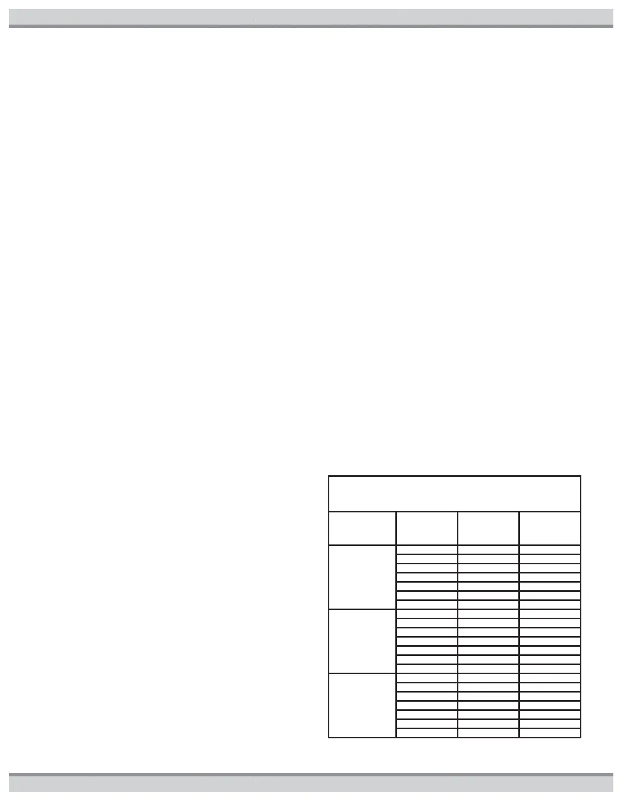
Table5 Combustion and Ventilation Air
Requirements (sq. in.)*
Free Area per
Total Btu
Requirement
Combustion
Air Free Area
Required
Ventilation
Air Free Area
Required
1
sq. in. per
1,000 Btu/hr
(Indoor Air)
1
sq. in. per
2,000 Btu/hr
(Outdoor Air thru
Horz duct)
1 sq. in. per
4,000 Btu/hr
(Outdoor Air
direct or thru Vert
duct )
*For detailed methods of providing combustion and ventilation air, see
latest edition of the National Fuel Gas Code (ANSI Z223.1/NFPA 54).
 Loading...