USE ONLY GENUINE REPLACEMENT PARTS 27
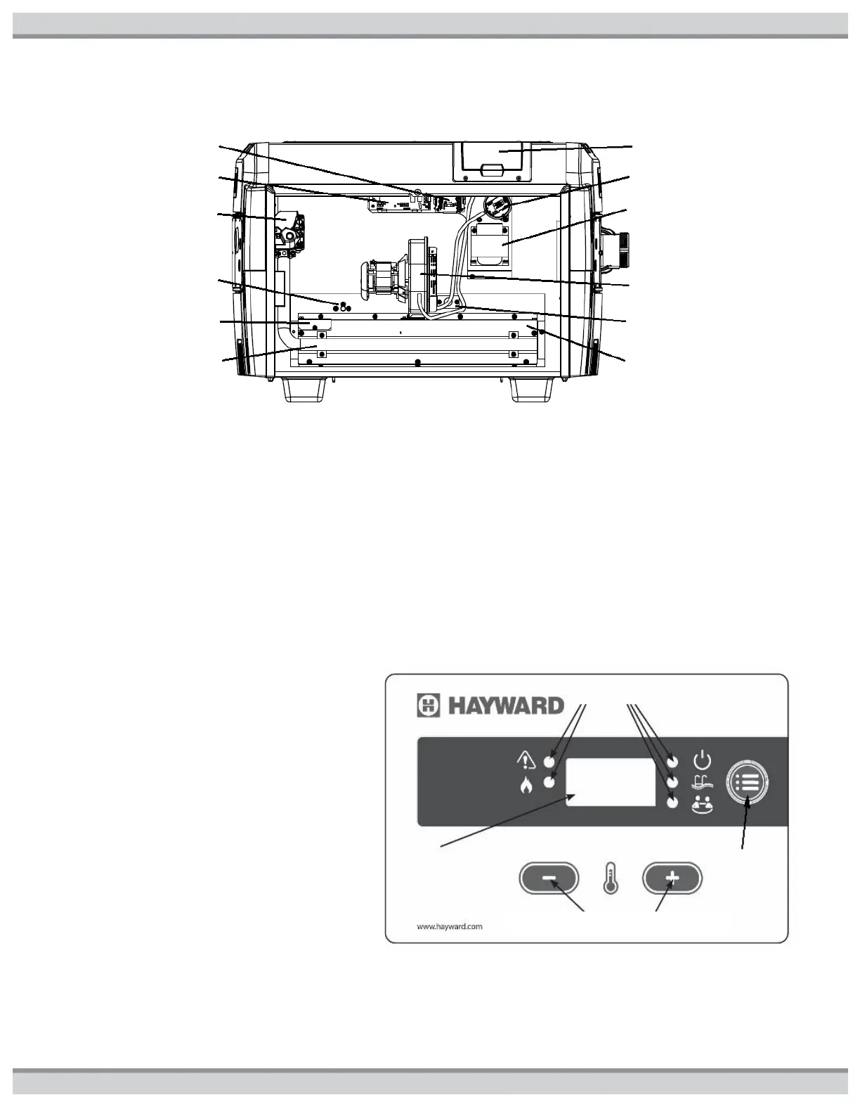
Figure23: Location of Components
CONTROL SETUP
This pool heater is equipped with a digital thermostat which allows the user to select the desired water temperature (see figure24).
The heater will then function automatically to maintain the desired temperature. The heater has 4 modes of operation:
1. STANDBY: in this mode, the heater will not function to heat the water.
2. SPA: in this mode, the heater will automatically function to maintain the water temperature setting for SPA mode.
3. POOL: in this mode, the heater will automatically function to maintain the water temperature setting for POOL mode.
4. BYPASS OPERATION “bo” is displayed. In this mode the heater will respond to a remote call for heat for set point control and
monitor the local thermostat for high return water temperature (maximum of 104°F).
Use the MODE button to change STANDBY/POOL/SPA modes. The indicator lights will illuminate to show which mode is currently
active.
USER PANEL AND KEYPAD INPUTS: The control
accepts user inputs via user panel (figure24).
1. When changing the mode from “STANDBY” to
either “SPA” or “POOL” (see Figure24) there
may be up to a 10- second delay before the
heater starts operating. The control performs an
internal self-test and then verifies that the
blower vacuum switch contacts are open before
energizing the blower.
2. It is normal for the heater to encounter a 1- to 2-
second delay in responding to any user panel
input.
3. It is normal for the heater to encounter up to a
5-second delay when the user panel is used to
reset the control to clear an error code.
4. The control will accept a mode change during
lockout after 5 seconds. The control will
continue to display the error code and remain in
lockout until it is reset. At reset the control will
go to the last saved mode.
Figure24: User Panel
Control and Selector Buttons