USE ONLY GENUINE REPLACEMENT PARTS 23
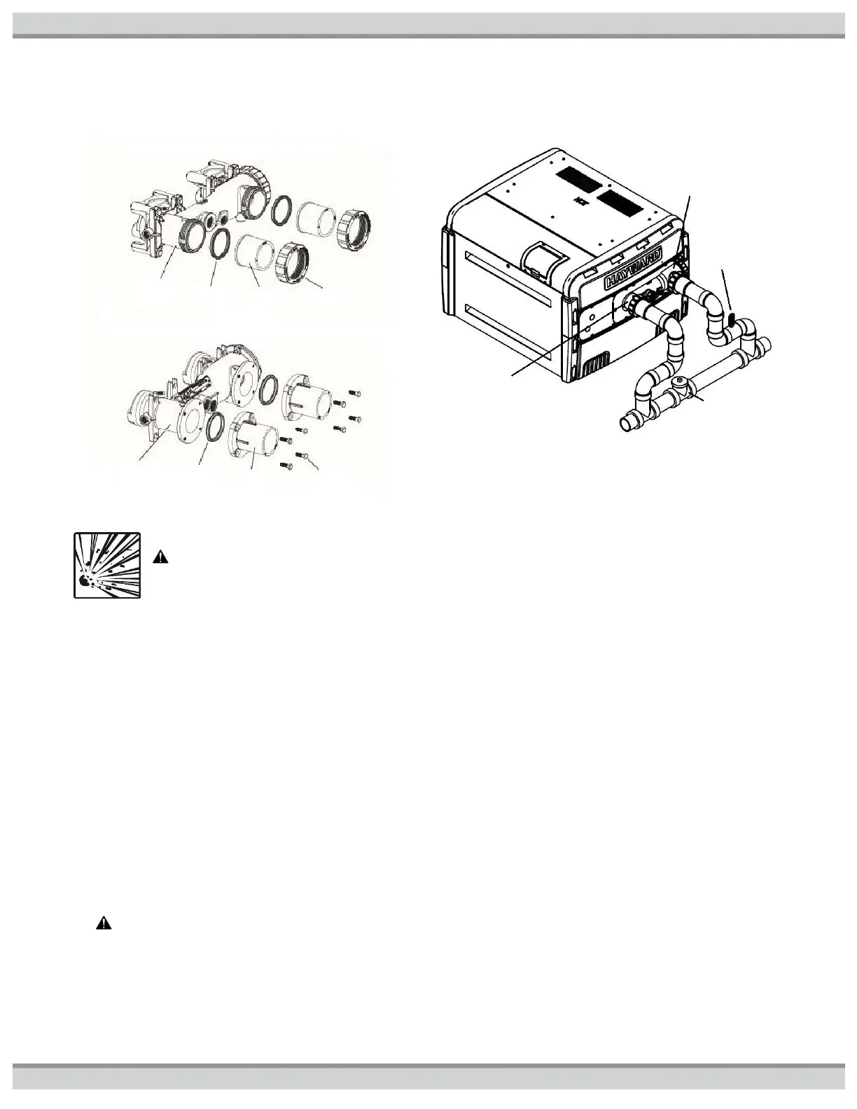
Figure15: Water Connections
Figure16: Bypass Valve(s)
WARNING: EXPLOSION HAZARD Blockage of water flow from heater return to pool may result in fire or
explosion causing property damage, personal injury, or loss of life.
The heater is equipped with CPVC flanged pipe nipples to accommodate water piping to and from the pool or spa. These pipe
nipples will accept piping by solvent welding (PVC glue). The fittings will accept either a 2”pipe, or a 2 1/2” pipe fitting, and seal to
the heater header with rubber gaskets. On plastic headers, the fittings are secured in place with supplied plastic union nuts, and on
bronze headers (ASME models), the fittings are secured in place with bolts. Assemble these parts to the heater prior to plumbing.
Tighten union nuts (or bolts) securely before gluing fittings to the ends of the pipe nipples. See Figure15. The CPVC flanged pipe
nipples must be installed on the heater inlet and outlet without modification. Pipe, fittings, valves, and any other element of the filter
system may be made of plastic materials, if acceptable to the authority having jurisdiction. Heat sinks, heat tapes, firemen switches,
and check valves are not required on the heater. However, if there is any chance of “back-siphoning” of hot water when the pump
stops running, it is suggested that a check valve be used on the heater outlet pipe down stream of bypass system. The built-in
bypass inside the header will maintain proper flow through the heat exchanger if the flow rate is within the range specified in the
specification in the Getting Started section. The minimum flow rate is to be calculated or measured with the in-floor cleaning system
in use, if the pool is so equipped, as well as any other jets or other demands on the water flow. If the normal pump and filter system
flow rate exceeds 125gpm then a manual bypass valve must be installed as shown in Figure16. Damage caused by flow rates
outside this range will void the manufacturer’s warranty. Bypass valve setting may be accomplished by temporarily installing a flow
meter on the outlet line of the heater. Then adjust the manual bypass valve until the flowrate through the heater is within the flow
rate range specified. Once the manual bypass valve is set, note the position and remove the valve handle to prevent accidental
adjustment.
CAUTION: Improperly adjusted manual bypass valves will result in damage to the heater if the flow rates are not
maintained under all operating conditions as specified in Table1: Specifications. The heat exchanger will fail and this
damage will not be covered under the manufacturer warranty.