12 USE ONLY GENUINE REPLACEMENT PARTS
EQUIPMENT PAD: Place the heater on a level surface such as concrete or a fabricated slab (pad). This allows proper
drainage of condensation and rainwater from the base of the unit. If possible, the pad should be placed at the same level or slightly
higher than the filter system equipment pad.
FLOORING: This heater may be installed on either non-combustible flooring or combustible flooring that does not reduce the
bottom clearance of the heater. Ultralite™ or equivalent concrete-over-foam HVAC pads are acceptable.
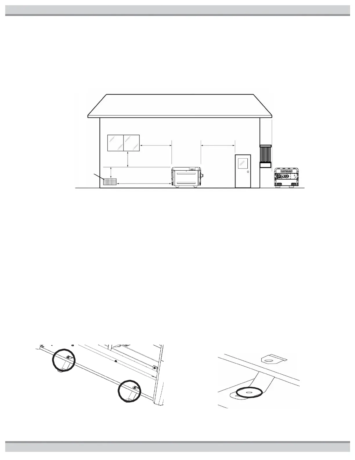
Figure5: Outdoor Minimum Clearances
ANCHORING: The heater is equipped for installation of factory supplied tie-down brackets when required by local codes.
Follow all relevant Local, State and National requirements regarding wind load anchoring. The brackets are shipped in the
consumer kit. You will need the following to complete the installation:
Tie-down brackets (FACTORY-SUPPLIED, qty = 4)
Sheet metal screws (FACTORY-SUPPLIED, qty = 4)
Concrete tapping screws (FIELD-SUPPLIED, Tapcons®, qty = 4, stainless steel, size to be ¼”diameter with a minimum
length of 1-1/2”)
Fender washers (FIELD SUPPLIED, stainless steel, qty = 4, size to be at least 1-1/2”)
INSTALLING TIE-DOWN BRACKETS:
1. Locate the tie-down brackets and the sheet metal screws.
2. Obtain the Tapcons®. Be sure the overall length of the concrete tapping screw is at least1-1/2”.
3. Remove the front (1 screw) and rear access panel (4 screws).
4. Position the heater on the pad so that all Tapcons® can “bite” into the pad. Observe local codes regarding pad construction,
some jurisdictions specify a minimum thickness for concrete pads.
5. Position the tie-down brackets into the slots in the front of the heater base pan so they are positioned as shown in Figure6. Install
the sheet metal screws through the holes in the bracket to secure the bracket to the heater base pan.
6. Install the Tapcons® through the inner set of holes in the tie-down brackets into the pad (see figure7).
7. Repeat Steps 6 & 7 at the rear of the heater.
8. Tie down is completed when (4) brackets are secured to the heater and the pad. Re-install the access panels in locations (front
and rear), front shown
Figure6: Tie-Down Installation Locations
Install supplied screws at these locations.
Figure7: Use 2nd Hole for Ground Mount of
Tie-Down Brackets with 2 Holes
Free
from rain
run off or
blockage
from
above