USE ONLY GENUINE REPLACEMENT PARTS 31
GAS PRESSURE TEST PROCEDURE: Follow the lighting instructions on the unit (or from Figure25). Refer to Figure23: Location
of Components for the location of the gas valve. See figure26 for pressure regulation adjustment for use in this procedure. Note
that even though the valves look different, the required pressure taps and regulation adjustment screws are present on every gas
valve.
1. Obtain the necessary equipment; Qty (2) manometers to
read pressure in inches of water column, Qty (2) 1/8”NPT
pipe barbed fitting, silicon or EPDM hose to fit on barb
fittings, 3/16” hex wrench, 7/16 open end wrench, and
medium flat screw driver.
2. Turn off gas supply to heater. Access the gas valve and
remove the 1/8” plugs from the gas valve inlet pressure
and manifold pressure taps and install the barb fittings
into the tap openings.
3. Securely connect the hoses and manometers to the barb
fittings. Make sure the manometers have ample range
and accuracy to properly read the gas inlet pressure and
manifold pressure per Table14.
4. Turn on gas and water to heater and start the heater
following the lighting & operating instructions on the label
affixed inside the front access panel. If there is more than
one pool/spa heater connected to the gas supply line, turn
each of those appliances “ON” while testing the heater.
5. Take pressure readings with the heater(s) running, the
pressure values should agree with those in Table14. If the
pressures are within the stated ranges, then no further
adjustment is needed. If the manifold gas pressure does
not meet the values in Table14, the gas valve regulator
must be adjusted.
6. To adjust the gas valve regulator perform the following:
a. Remove the screw cap over the regulator adjustment
screw (see Figure26).
b. Turn the inner regulator adjustment screw clockwise
to increase pressure and counterclockwise to
decrease pressure as required.
c. Replace the screw cap over the regulator adjustment
screw.
d. Cycle the heater on/off multiple times and repeat
measurements to ensure regulation springs are set.
NOTICE: If proper pressures cannot be achieved by
adjusting the gas valve regulator, the installer must contact
the gas supplier and request that the inlet pressure to the
heater(s) be provided to within the gas pressure range listed.
7. Remove the barb fittings and replace the original 1/8” pipe
plugs. Turn on gas and water to heater and start the
heater to check for gas leaks.
Table14: Required Gas & Air Pressures
(inwc)
Vent Pressure,
(Models150-400)
maximum
Vent Pressure,
(Model-500)
maximum
*Pressure range for allowable heating value variation.
WARNING: EXPLOSION HAZARD Do not remove the measurement tap screws with the valve in the “ON”
position and gas supplied to heater. No gas pressure must be present when the taps are open to atmosphere.
Removal of the taps screws or barb fittings with gas present could cause an explosion resulting in severe injury
and/or death.
WARNING: EXPLOSION HAZARD Gas pressures in excess of those listed in Table14 could cause a gas leak or
diaphragm rupture. Gas leakage could cause an explosion resulting in severe injury or death.
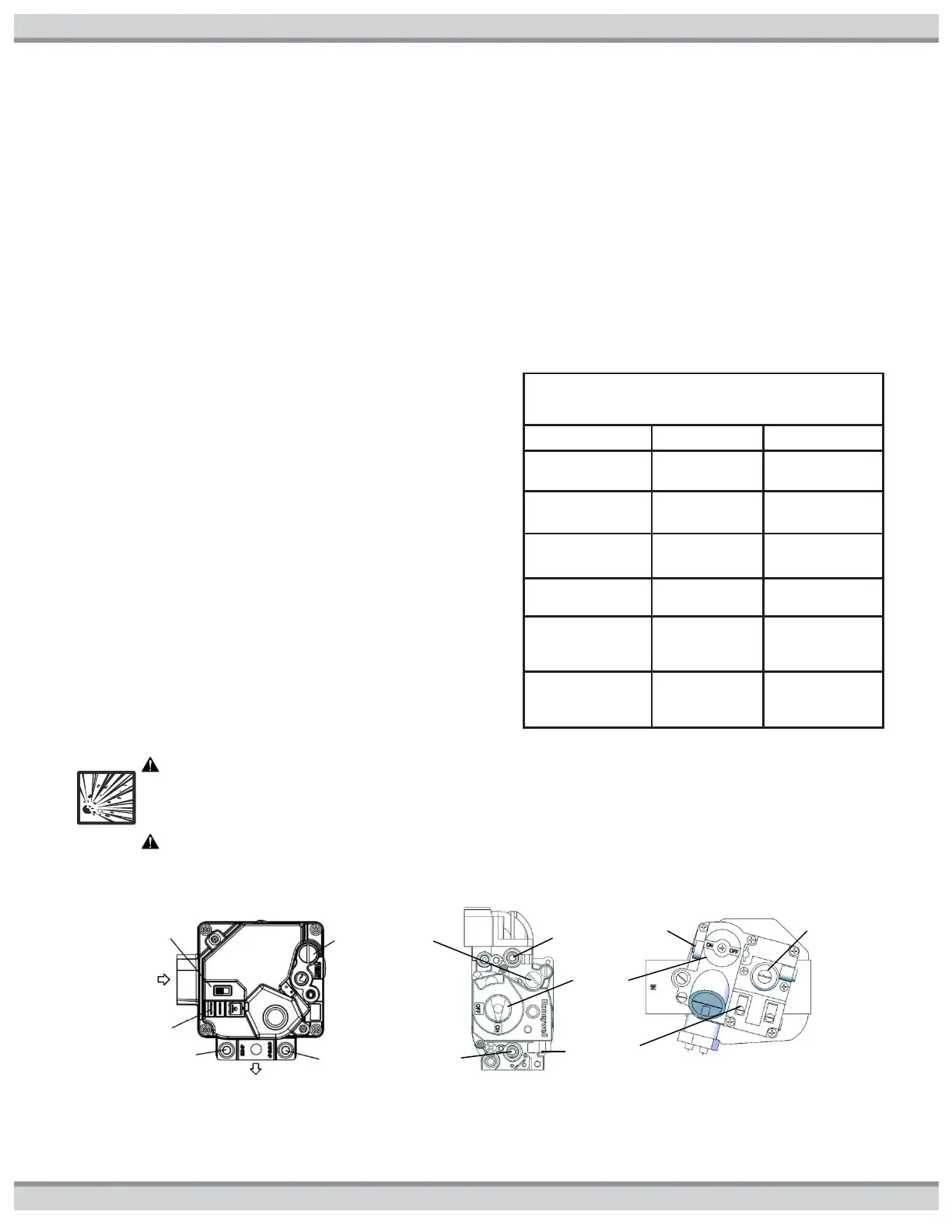
Figure26: Gas Valves
For all valves, adjust regulator pressure by removing the screw cap and turning the adjustment
screw clock wise for increase in pressure and counter clock wise for decrease in pressure
Regulator
adjustment
under cap
Regulator
adjustment
under cap

 Loading...