USE ONLY GENUINE REPLACEMENT PARTS 35
SERVICE OF HEATER: The following service procedures: HEAT EXCHANGER INSPECTION AND CLEANING and BURNER
INSPECTION AND CLEANING are recommended to be performed as part of annual heater maintenance to ensure proper heater
operation and long life.
HEAT EXCHANGER INSPECTION AND CLEANING: Remove the louvered exhaust cover panel (see Figure1: Sub-Assemblies)
and inspect the external surfaces of the heat exchanger for debris or soot accumulation. If heat exchanger needs cleaning perform
the following procedure:
WARNING: BURN HAZARD: Let heater cool before performing any disassembly or servicing of the heater.
Wear proper PPE when servicing heater.
1. Turn pump, main gas valve and heater power “OFF”. Perform only DRY cleaning with heat exchanger in heater. WET cleaning
requires that the heat exchanger be removed from heater.
2. For DRY cleaning remove debris by hand, soft-tipped brush or shop VAC.
3. For WET cleaning remove heat exchanger by following the “Reversible Water Connections” procedure found in the WATER
PIPING section of this manual. Use a soft-tipped brush (such as a paint brush), to apply a degreaser to the entire heat
exchanger surface (top and bottom). Allow the heat exchanger to sit for a period of time to allow the degreaser to loosen the
debris. Wash the heat exchanger using a garden hose at a medium to low pressure setting. Ensure both the top and bottom
surfaces are cleaned.
4. Check combustion chamber refractory is still in a single-piece casting with no cracks or holes. This evaluation can be performed
with heat exchanger in place with additional lighting or with heat exchanger removed from unit. If combustion chamber
refractory is damaged, the entire chamber must be replaced.
5. Re-assemble the heater by reversing the disassembly steps. Turn pump, main gas valve and heater power “ON”. Test fire
heater.
NOTICE: Although the heat exchanger should be cleaned of soot and reinstalled, the fact that soot occurred should be
investigated. It may indicate other problems such as: Insufficient air supply; Inadequate venting; High or low gas pressure;
Blockage of burner tubes or orifices; Blockage of blower inlet; Low voltage supply causing blower to “spin” slower; Improper
heater location / installation; Incorrect gas supply pipe size; Excessive water flow through heat exchanger; Or an LP tank below
30% full level.
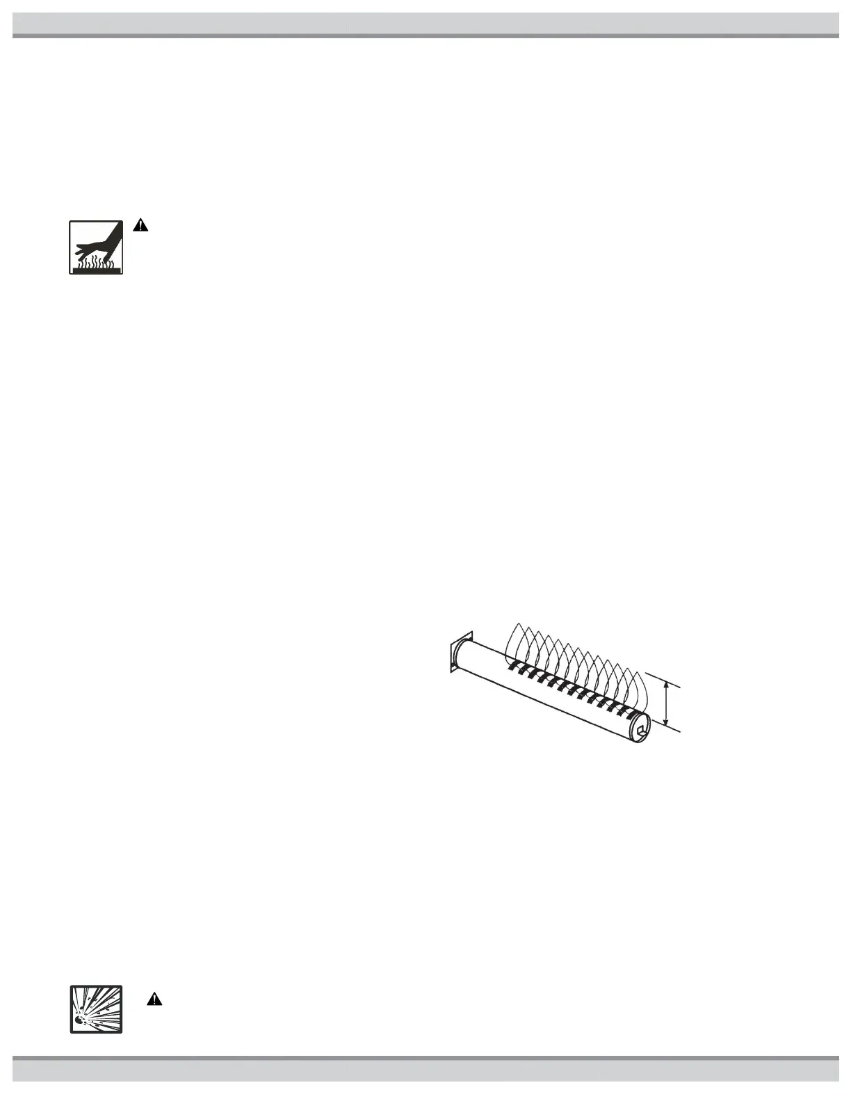
BURNER INSPECTION AND CLEANING: With the heater
“ON”, remove the front access panel and make a visual
inspection of the main burners through the sight glass (see
Figure23: Location of Components.) The main burner flames
should be about 1” to 2” in height and should not “lift” off the
burner ports (see Figure29: Burner Flame Characteristics). A
normal flame is blue, without yellow tips. Yellow tips or a
totally yellow or “lazy” flame may be an indication of an
incorrect fuel / air mixture. Check the heater for restrictions
to the air supply, heat exchanger, vent system, burner body
and/or gas orifices.
Figure29: Burner Flame Characteristics
BURNER REMOVAL AND REPLACEMENT: Refer to Figure1, Figure12, and Figure23 as needed.
1. Turn pump, gas supply, and heater power “OFF”. Turn gas valve knob “OFF”.
2. Remove the front access panel.
3. Disconnect the union joint in the gas supply piping outside the heater cabinet.
4. Disconnect the wiring terminals from the gas valve and blower
5. Remove the gas manifold assembly. It is attached to the air box using (4) screws.
6. Remove the screws from the igniter access panel and pull it out of the way. Do not disconnect the wires.
7. Remove the air box cover. Do not remove the blower from the air box cover.
8. Remove the (2) screws securing each burner to the combustion chamber front.
9. Pull the burners straight out of the heater.
10. Reverse the above procedure to re-install the burners.
11. Turn the gas supply “ON”. Use a soapy water solution to check for leaks. Bubbles forming indicate a leak.
WARNING: EXPLOSION HAZARD The use of an open flame to check for gas leaks could cause an explosion
resulting in severe injury and/or death

 Loading...