AED9101D
20 I3563-1.0 en
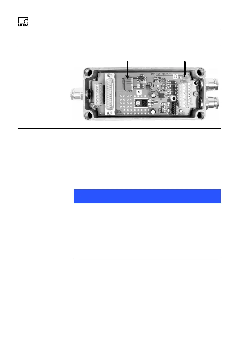
Interface configuration, DIP
switches S1 to S6
Bus termination
Fig. 6.7 DIP switch positions for the interface configuration
The interface cable shield must not be connected to GND
or to the supply ground, but to the housing of the AED
(see Section 6.8 on page 29).
The sections that follow contain more connection inform-
ation.
Note
With longer cables (over 30m, only possible with RS‐422
and RS‐485), there is a risk that the individual bus nodes
will have different ground potentials. The interface allows
a maximum common-mode range of -7 0 12 V, related
to GND. If these values could possibly be exceeded, a
separate line must be used to establish potential equaliz
ation between the bus nodes.
A flexible cable with a conductor cross-section of at least
10mm
2
is the best choice for potential equalization.