AED9101D
I3563-1.0 en 19
drop depends on the supply current and on the line res-
istance.
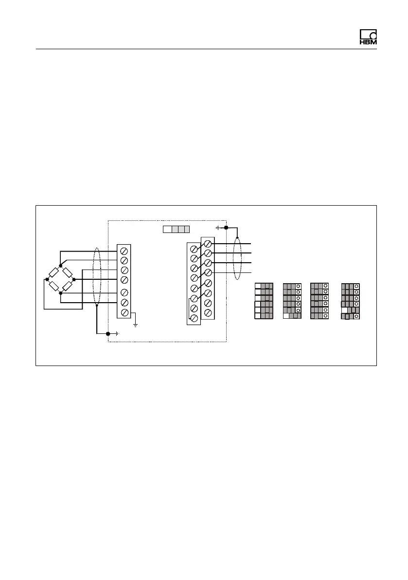
6.3 Connection to a PC
The basic device has an interface that can be operated in
different configurations. You can select one of them for
communication and data transmission. The choice is
made via several DIP switches (S1 to S6).
AED9101D
Bus termination
Equivalent interface cable
designations:
TA = T- TB = T+
RA = R- RB = R+
RS‐232
RXD
TXD
DTR
GND
RS‐422
TB
TA
RB
RA
RS-485
4-wire
TB
TA
RB
RA
RS-485
2-wire
TB/RB
TA/RA
S1
S2
S3
S4
S5
S6
TE1
TE4
1
2
16
1
15
7
Fig. 6.6 Pin assignment and switch positions for the various
interfaces
Again use shielded cables for the interface cables, with
the cable shield connected to the AED housing via the
PG gland (see Sections 6.7 and 6.8, starting on page
28). The voltage supply can also be routed via this cable,
which means that a 5 or 6-wire, shielded cable is
required, depending on the interface. EMC reasons make
it an advantage to use a double-shielded cable, such as
HBM type 4-3301.0071, at 3 2 0.14 m
2
.