AED9101D
I3563-1.0 en 23
you can connect several AEDs to one interface on the
PC (bus mode, see Section6.4).
For 4‐wire connection, slide DIP switches S1 to S6 to the
left. For 2‐wire connection, slide S1 to S4 and S6 to the
left, S5 to the right. The switch position for bus termina-
tion (termination) is geared to the position of the AED in
the bus system, see Section 6.4, page 23.
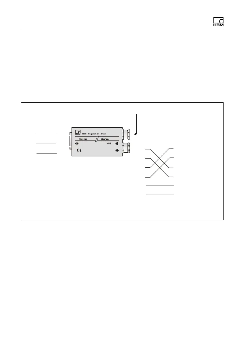
RS‐232
8...30 V
2/4-wire
RS‐485
TxD
RxD
GND
RxD
TxD
GND
Interface converter
RS‐232 - RS‐485
PC COM port
D-Sub plug, 9-pin
(PC)
PIN
2 = RxD
3 = TxD
5 = GND
U
v
: 10 30V
DC
RS‐485 bus
TA
TB
RA
RB
GND
Uv
TA (blue)
TB (black)
RA (green)
RB (gray)
GND
U
v
(red, 10 ... 30V
DC
)
(white)
Equivalent designations:
TA = T-
RA = R-
TB = T+
RB = R+
D-Sub socket, 9-pin
(converter)
PIN
2 = TxD
3 = RxD
5 = GND
AED
Fig. 6.9 Connecting an AED (RS422 or RS4854wire) to a
PC via the HBM interface converter; also see
Fig. 6.6 on page 19
6.4 Using several AEDs (bus mode
with RS‐485)
Up to 89 AEDs can be connected via the RS‐485 inter-
face to a common bus line, the total length of which can