T12
40
A1979−10.0 enHBM
Important
If plug 1 is used to power the device a tape wound core (toroidal core) is nec-
cessary to suppresse high frequencies in order to ensure compliance with
FCC regulations
NOTE
Torque transducers are only intended for operation with a DC supply voltage
(separated extra-low voltage), see page 43.
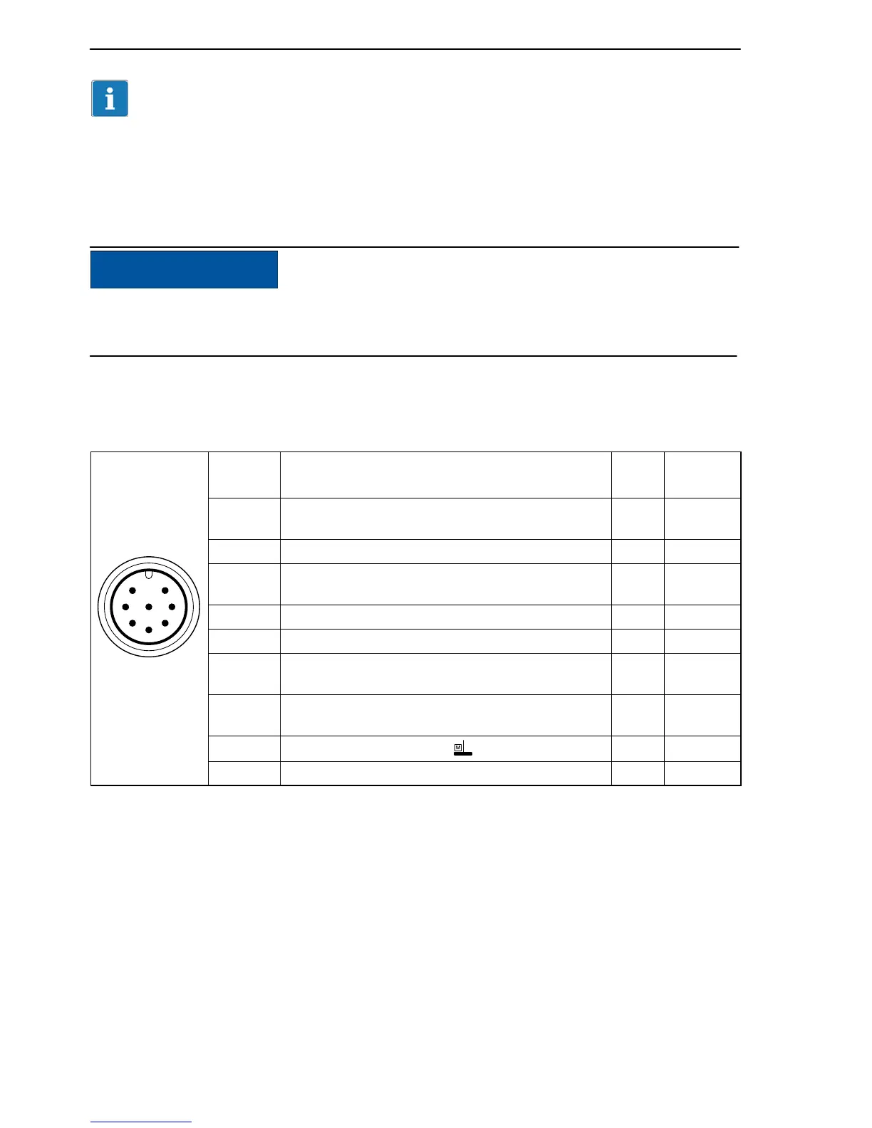
Assignment for plug 2:
Rotational speed measuring system
Binder 423
device plug
Top view
7
3
4
6
2
5
1
8
Plug
pin
Assignment Color
code
Sub-D
plug pin
1 Rotational speed measurement signal
(pulse string, 5 V
1)
; 0)
rd 12
2
Not in use
bu 2
3 Rotational speed measurement signal
(pulse string, 5 V
1)
; phase-shifted 90) gy 15
4 Not in use bk 3
5
TEDS for rotational speed
vt 9
6 Rotational speed measurement signal (pulse
string, 5 V
1)
; 0)
wh 13
7
Rotational speed measurement signal
(pulse string, 5 V
1)
; phase-shifted 90
)
gn 14
8
Measurement signal 0 V
bk
2)
8
Shielding connected to housing ground
1)
RS−422 complementary signals; with cable lengths exceeding 10 m, we recommend
using R=120 ohms termination resistors between wires (rd) and (wh), as well as (gy)
and (gn).
2)
Color code brown (br) for Kab 163 and Kab 164.
 Loading...