41
T12
A1979−10.0 en HBM
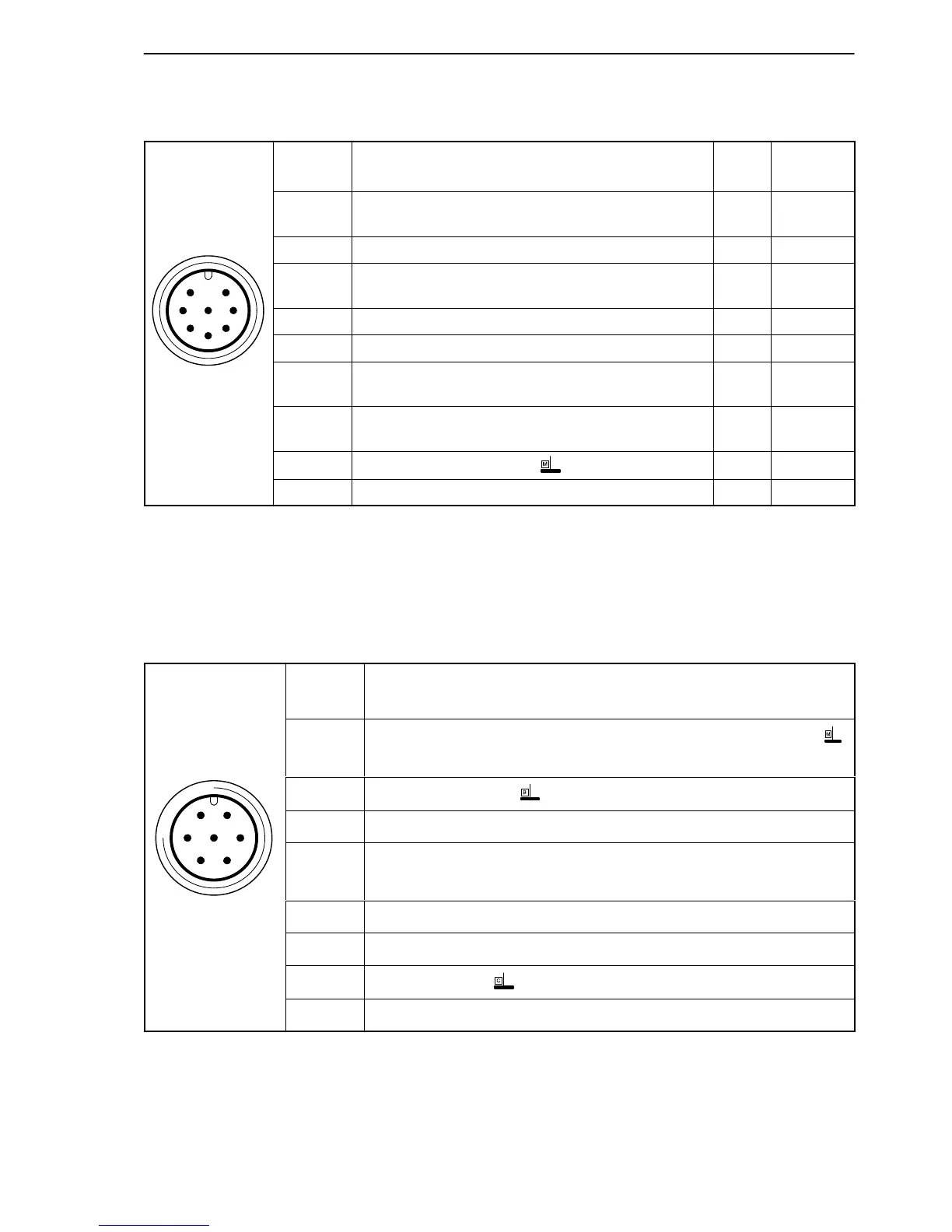
Assignment for plug 2:
Rotational speed measuring system with reference signal
Binder 423
device plug
Top view
7
3
4
6
2
5
1
8
Plug
pin
Assignment Color
code
Sub-D
plug pin
1 Rotational speed measurement signal (pulse
string, 5 V
1)
; 0)
rd 12
2
Reference signal (1 pulse/rev., 5 V
1)
)
bu 2
3 Rotational speed measurement signal
(pulse string, 5 V
)
; phase-shifted 90) gy 15
4 Reference signal (1 pulse/rev., 5 V
1)
) bk 3
5
TEDS for rotational speed
vt 9
6 Rotational speed measurement signal (pulse
string, 5 V
1)
; 0)
wh 13
7
Rotational speed measurement signal
(pulse string, 5 V
)
; phase-shifted 90)
gn 14
8
Measurement signal 0 V
bk
2)
8
Shielding connected to housing ground
1)
RS−422 complementary signals; with cable lengths exceeding 10 m, we recommend
using R=120 ohms termination resistors between wires (rd) and (wh), (bu and (bk), (gy)
and (gn).
2)
Color code brown (br) for Kab 163 and Kab 164.
Assignment for plug 3:
Supply voltage and voltage output signal.
61
5
72
4
3
Binder 423
device plug
Top view
Plug
pin
Assignment
1
Torque/rotational speed measurement signal (voltage output; 0 V )
or rotational speed measurement signal (0 V)
2
Supply voltage 0 V;
3 Supply voltage 18 V to 30 V DC
4
Torque measurement signal (voltage output; "10 V)
or rotational speed measurement signal ("10 V)
5 Not in use
6 Shunt signal trigger 5 V to 30 V and TEDS for torque
7
Shunt signal 0 V;
Shielding connected to housing ground
 Loading...