EasyManua.ls Logo

Heart Interface LINK 2000 - User Manual

Heart Interface LINK 2000
36 pages
Print Icon
To Next Page IconTo Next Page
Loading...
5/31/96
1
ONLINE OWNERS MANUAL
LINK 2000
Manual Part # 890024Copyright 1994-96
INSTALLERS!!! THIS DOCUMENT IS IMPORTANT FOR
OPERATION, PLEASE LEAVE IT WITH THE OWNER!!!
The LINK 2000 is an integrated battery monitor and inverter/
charger control. It displays the critical information necessary for 12V
or 24V DC system battery management and allows precise control of
critical inverter and charger features.
The LINK 2000 may be used as a stand-alone battery monitor or
with the following inverter/chargers from HEART INTERFACE:
FREEDOM 10 INVERTER/CHARGERS
FREEDOM 15 INVERTER/CHARGERS
FREEDOM 20 INVERTER/CHARGERS
FREEDOM 25 INVERTER/CHARGERS
FAST START: For installation details skip to the Required
Reading section on page 34. Please read manual prior to using.
All warranty issues must be resolved through Heart Interface or Cruising
Equipment Co. Please do not return to the retailer, or route warranty issues
through the retailer.
21440 68
th
Ave. So. Kent, WA 98032
(206) 872-7225 Toll Free 1-800-446-6180
Mfg. by Cruising Equipment Co. 6315 Seaview Ave. NW Seattle, WA 98107 (206) 782-8100
C:\work\link\link2000new\newinstall.pm6
Question and Answer IconNeed help?

Do you have a question about the Heart Interface LINK 2000 and is the answer not in the manual?

Heart Interface LINK 2000 Specifications

General IconGeneral
BrandHeart Interface
ModelLINK 2000
CategoryMonitor
LanguageEnglish

Summary

Introduction and Special Notes

Important Operational and Installation Notes

Key precautions and directives for safe operation and installation.

Monitor Functions

VOLTS, AMPS, A hrs, and TIME

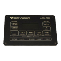
Explains the functions of VOLTS, AMPS, A hrs, and TIME displays.

Inverter;Charger Functions

Invert and Charge Functions

Details on enabling the Invert and Charge functions of the unit.

Marine and RV Operating Tip

Advice on managing loads and battery charging during utility outages.

Status Line

Status Line Indicators

Description of the four LED status indicators for AC power and charger state.

Starting and Stopping Equalize

Equalize Cycle Procedure and Safety

Steps to start, terminate, and safety precautions for the equalize cycle.

Set Up

Summary of Factory Default Values

Lists default settings for Inverter/Charger and Monitor functions.

Inverter Set Up

Idle Mode and Power Sharing Setup

Configuration of Inverter Idle Mode and Power Sharing features.

Monitor Set Up

Battery Parameter Setup (Voltage, %Current, Capacity)

Guide to setting Charged Voltage, Charged Current %, and Battery Capacity.

Functions Set Up

Function Setup Overview (F01-F15)

Overview of available functions and their setup procedures.

F02 - BATTERY TYPE

F03 - SET AMBIENT BATTERY TEMPERATURE

F04 - TOGGLE DISPLAY BETWEEN A HR AND KWHR

F05 - ALTERNATIVE ENERGY MODE

F06 - MANUALLY SET CEF (NOT RECOMMENDED)

F07 - SET TEMPERATURE COEFFICIENT

F08 - SET PEUKERTS EXPONENT

F09 - A HR OR % REMAING MODE

F10;F11 - Alternator Limit & Battery #2 Control

F12 - BACKLIGHTING INTENSITY CONTROL

F13 - F14 NOT USED

F15 - Special Function for use by Cruising Equipment.

Data

Historical Data Review (CEF, Recalculations, Discharges)

Review of historical data like CEF, recalculations, and discharge depths.

How to Use Link 2000 Meters

Battery Management Philosophy and Two Battery Systems

Philosophy on recharging and managing two-battery systems.

Over-Charge Amp-Hours Explanation

Explains accumulation of over-charge Amp-hours and its implications.

Battery Capacity Testing

Using Your Inverter to Test Battery Capacity

Ideal Charge Curve

Factory Default Charging Values

Synchronizing Link 2000 Meters to a Charged Battery

Charged Parameters and Synchronization Methods

Parameters for full charge and two methods for meter synchronization.

Resetting A hrs to Zero

Selecting the Charged Parameters

Should You Change the Charged Parameters?

Selection Rules

Advanced Functions

Troubleshooting Indicators (Low Bat, OL, Software Info)

Displays inverter shutdown counts, software revision, and display test.

Reset to Factory Defaults

Resets all user-configured settings to factory defaults.

High Discharge Rates & Peukerts Equation

Percentage of Available Capacity vs. Discharge Rate and Exponent

Typical Peukerts Exponents (Prevailer & SeaGel; Trojan)

Typical Peukerts Exponents (Surrette and Rolls)

Calculating Peukerts Exponent

Error Codes and Trouble Shooting

Error Codes E-1 through E-9

Definitions for error codes E-1 to E-9 related to system faults.

Error Codes and Trouble Shooting (Continued)

Error Codes E-10 through E-15

Definitions for error codes E-10 to E-15 related to system faults.

Verify Current Measurement

Procedure to verify current measurement accuracy using a multimeter.

Microprocessor Reset Procedure

Resetting Memory to Factory Values

Set Up & Historical Data Summary

Limited Warranty

Required Reading!

General Installation Notes and Shunt Caution

General wiring notes and critical caution for shunt sense leads.

Battery Current Sensing and Marine Notes

Explanation of current sensing via shunt and marine installation notes.

Wire by Wire Installation

Ground, Power, and Battery #1 Wiring

Details for connecting Black, Red, White, and Blue wires for installation.

Battery #2 and Shunt Wiring

Details for connecting Violet, Green, and Orange wires for installation.

Wire by Wire Installation (Continued)

Battery #2 and Shunt Wiring (Continued)

Details for connecting Brown and Yellow wires for installation.

The Inverter Phone Cord

Related product manuals