Page
1
3
Heathkit
STEP-BY-STEP
ASSEMBLY
Refer
to
Pictorial
1-1
(Illustration
Booklet,
Page
2)
as you
read
the following
notes
and
steps.
and solder the leads to the
foil on the other side
unless
a step
specifically directs you
otherwise.
NOTES:
1.
such
2.
shown in Pictorial
1-1, are divided into
two
or more
sections. These sections
show you
which area
of the circuit board
you are work-
ing in for a
specific series of steps.
Refer to
the "Taped
Components Chart." Note
that
it is divided
into numbered sections
that
match the
sections on the
circuit board.
3.
4.
5.
Each
series of steps
has
you
installing parts
in a
top-to-bottom, left-to-right
sequence. Oc-
casionally, you may be
directed to
install
a
component in an
area out of sequence.
These
components are each identified
in the step
and on the
Pictorial with a special callout.
Check off each step as you
perform it. You
may also wish to
place a check
mark near each
component on the
Pictorial
as you
install it.
In general,
solder instructions are
given only
at the
end of a
series of similar steps. You
may solder more
often, if you desire.
In
the following steps,
you will be
given detailed
instructions on
how to
install
and
solder the first
part on
the circuit board.
Read and perform each
step carefully.
Then use the same
procedure when-
ever you install parts
on a circuit board.
(
)
Note that the circuit
board has foil on one
side
and component
outlines on the other. The
side
with the component
outlines is referred to as
the "component
side."
shown
with the component
side
up.
Always
install compo-
nents on the component
side of the circuit
board,
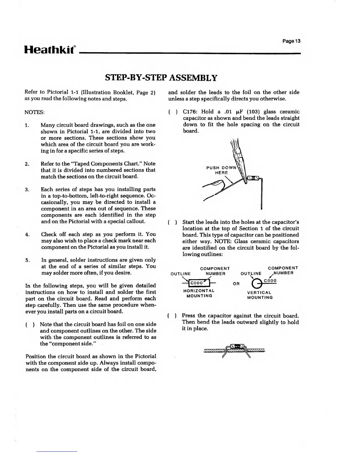
(
)
C176:
Hold
a
.01 u.F
(103)
glass ceramic
capacitor as shown and bend the leads straight
down to fit
the
hole
spacing
on the circuit
board.
PUSH
DOWN
HERE
(
)
Start the leads into the
holes
at
the capacitor's
location at the top of Section 1 of the circuit
board. This type of capacitor can be positioned
either way. NOTE:
Glass ceramic capacitors
are
identified on the circuit board by the fol-
lowing outlines:
OUTLINE
COMPONENT
NUMBER
OUTLINE
OR
HORIZONTAL
MOUNTING
COMPONENT
^NUMBER
C000
VERTICAL
MOUNTING
(
)
Press
the capacitor
against the circuit
board.
Then bend
the leads
outward slightly
to
hold
it in
place.