Heathkit
Page
51
STEP-BY-STEP
ASSEMBLY
Refer to Pictorial
3-1
(Illustration
Booklet, Page
19)
for the following
steps.
(
)
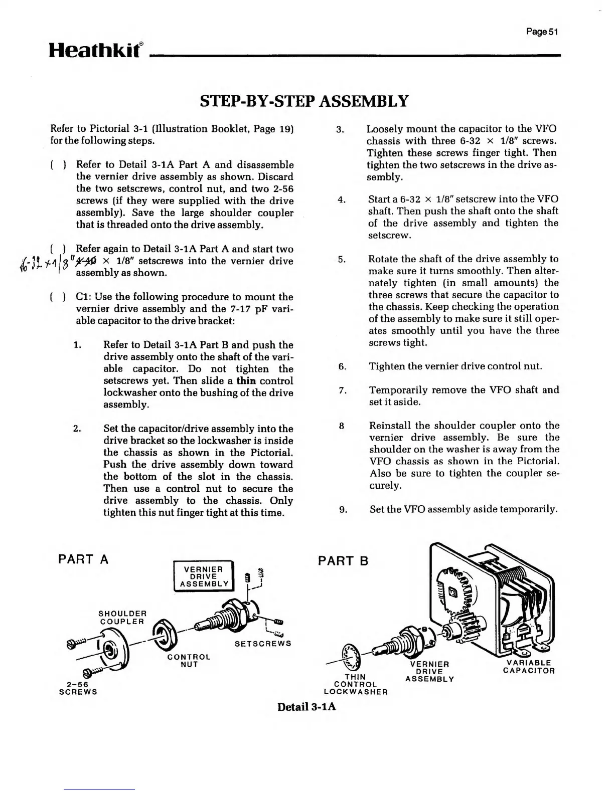
Refer to Detail
3-1A Part A and
disassemble
the vernier
drive assembly
as shown. Discard
the
two setscrews, control
nut, and two
2-56
screws (if they were
supplied with the drive
assembly). Save
the large shoulder
coupler
that is threaded
onto the drive assembly.
(
)
Refer again
to
Detail
3-1A Part A
and start two
*f.j\\fl*ffy0
x
1/8"
setscrews
into the vernier drive
'
assembly
as shown.
(
)
Cl: Use the following
procedure to mount
the
vernier
drive assembly and
the
7-17
pF vari-
able capacitor
to the drive bracket:
3.
1.
2.
Refer to Detail
3-1A Part B and
push the
drive
assembly onto the
shaft of the vari-
able
capacitor. Do not tighten
the
setscrews
yet. Then slide a thin control
lockwasher
onto the bushing
of the drive
assembly.
Set the capacitor/drive
assembly into the
drive bracket
so the lockwasher is inside
the
chassis as shown in
the Pictorial.
Push
the drive assembly down
toward
the bottom of the slot
in the chassis.
Then
use a control nut
to secure the
drive assembly
to the chassis. Only
tighten this nut finger
tight at this time.
4
5
6
7
8
Loosely
mount the capacitor to the
VFO
chassis
with three
6-32 X
1/8"
screws.
Tighten these
screws finger tight. Then
tighten the
two setscrews in the drive as-
sembly.
Start a
6-32 x
1/8"
setscrew into the VFO
shaft. Then push the
shaft onto the shaft
of
the drive
assembly and tighten the
setscrew.
Rotate the shaft
of the drive assembly to
make sure it turns
smoothly.
Then
alter-
nately
tighten (in small amounts) the
three
screws that
secure the capacitor to
the
chassis. Keep checking the
operation
of the assembly to
make sure it still oper-
ates
smoothly until you have the three
screws tight.
Tighten
the vernier drive control nut.
Temporarily
remove the VFO shaft and
set it aside.
9.
Reinstall the shoulder coupler onto the
vernier
drive assembly. Be sure the
shoulder on the
washer is away from the
VFO
chassis as shown in the
Pictorial.
Also be
sure to tighten the
coupler se-
curely.
Set the VFO
assembly aside
temporarily.
PART
A
SHOULDER
COUPLER
PART
B
SETSCREWS
CONTROL
NUT
2-56
SCREWS
THIN
CONTROL
LOCKWASHER
VERNIER
DRIVE
ASSEMBLY
VARIABLE
CAPACITOR
Detail
3-1
A