Page
72
Heathkif
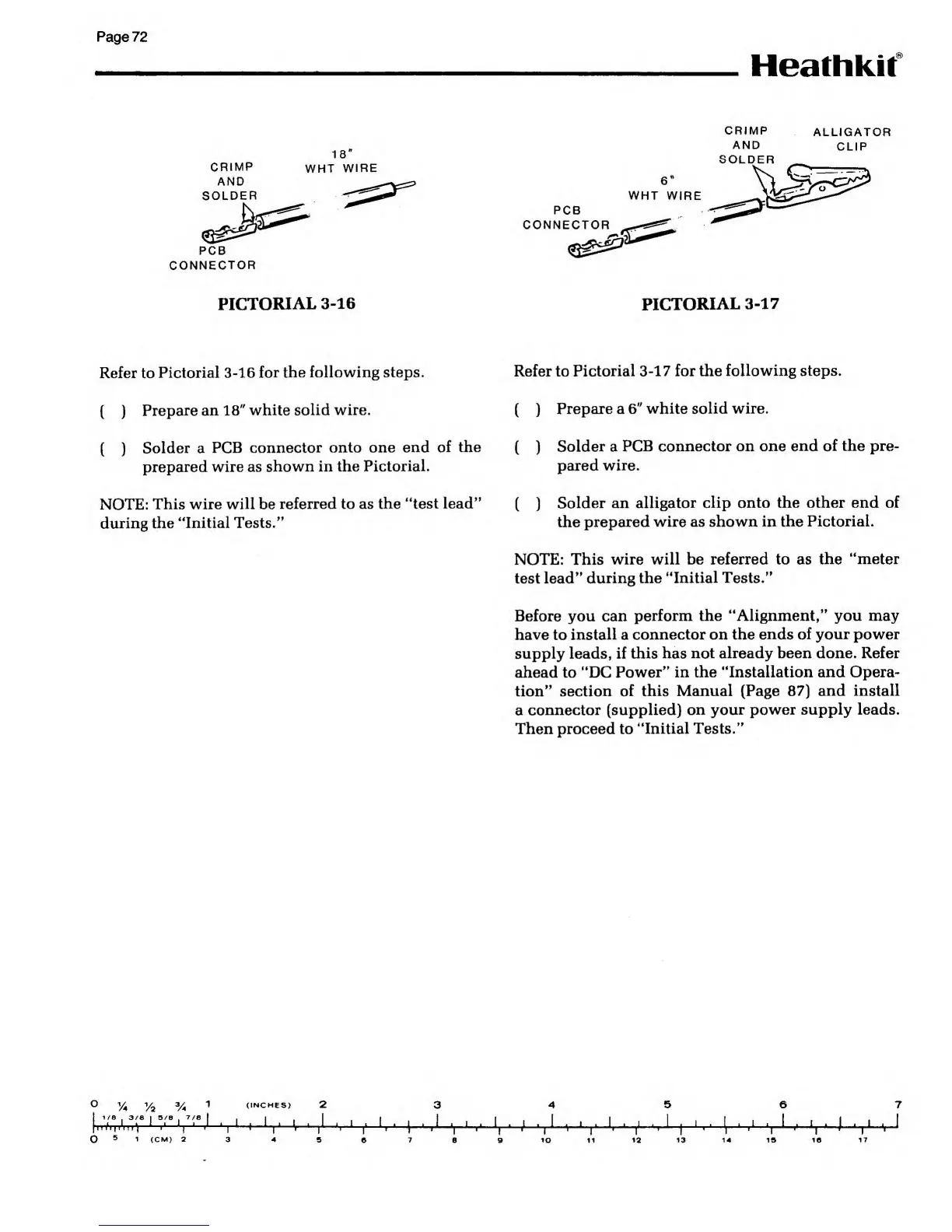
CRIMP
AND
SOLDER
PCB
CONNECTOR
18"
WHT
WIRE
PCB
CONNECTOR
WHT WIRE
CRIMP
AND
SOLDER
ALLIGATOR
CLIP
PICTORIAL
3-16
PICTORIAL
3-17
Refer to
Pictorial
3-16
for the following steps.
Refer to
Pictorial
3-17
for the
following steps.
( )
Prepare an
18"
white
solid wire.
( )
Prepare a
6"
white solid wire.
(
)
Solder a
PCB
connector onto one end
of the
(
)
Solder a
PCB connector on one
end of the pre-
prepared wire as
shown in the
Pictorial.
pared
wire.
NOTE:
This wire
will
be
referred to as the
"test lead"
during the
"Initial Tests."
(
)
Solder an
alligator clip onto the other end of
the prepared
wire as shown in the
Pictorial.
NOTE: This
wire will be referred to as
the "meter
test lead"
during the
"Initial Tests."
Before you can
perform the "Alignment," you may
have
to
install
a
connector on the
ends of your power
supply leads, if this has
not already been done. Refer
ahead to "DC
Power" in the "Installation and Opera-
tion" section
of this Manual (Page
87)
and install
a
connector (supplied) on
your power supply leads.
Then proceed to
"Initial Tests."
o
(INCHES)
1/8 .
3/8 I 5/B
,
7/8
I i
1
t
I
|
HIT |T
ITI
V4
1
i'
' '
i'
It*
+
'|
1
i'
I-
1 a.
1