Page 74
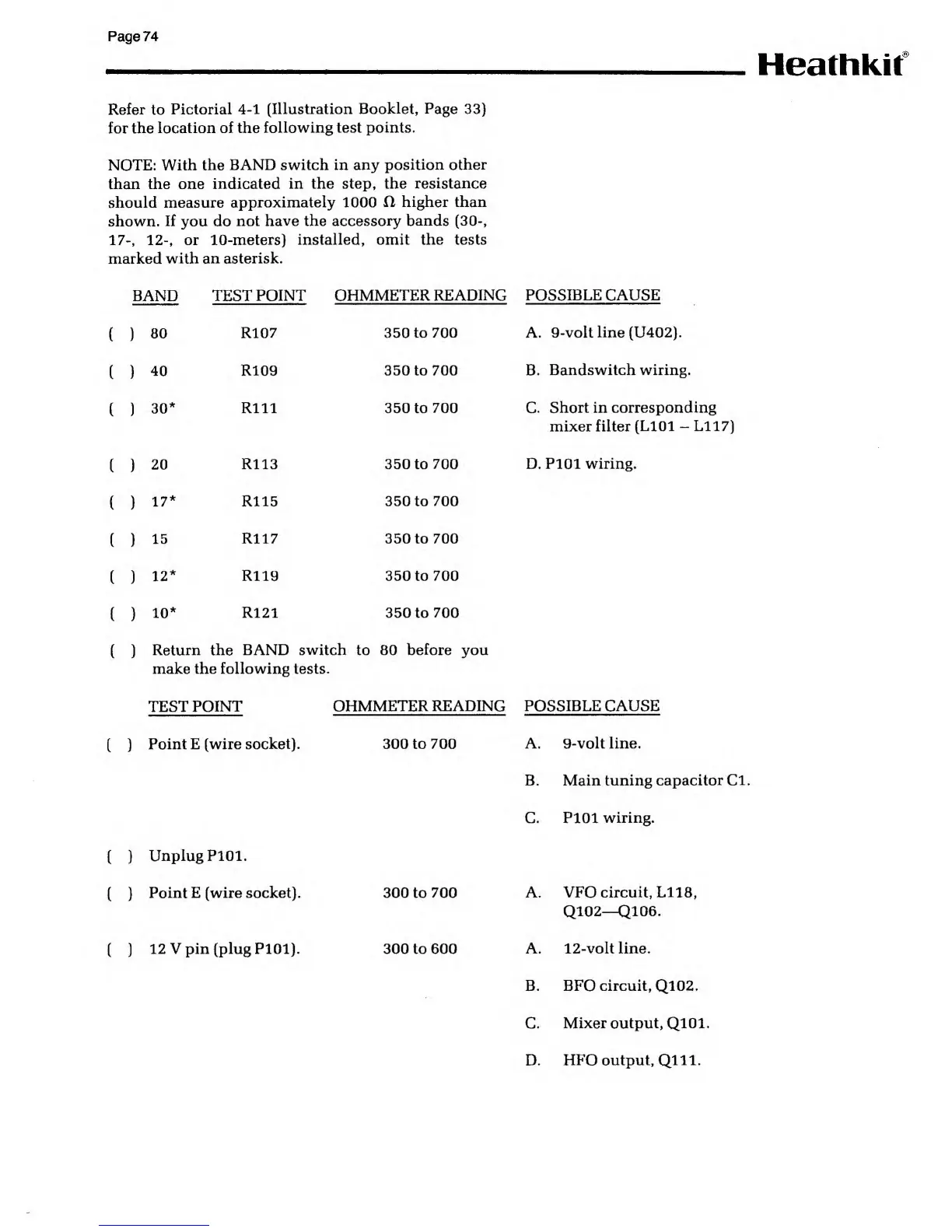
Refer
to
Pictorial
4-1
(Illustration
Booklet, Page
33}
for
the location of the
following test points.
NOTE: With
the BAND switch in any
position other
than the one
indicated in the step, the
resistance
should measure
approximately 1000
fl higher than
shown.
If
you do
not
have
the
accessory bands (30-,
17-,
12-,
or
10-meters) installed, omit the tests
marked
with an asterisk.
Heathkit
BAND TEST
POINT OHMMETER
READING POSSIBLE CAUSE
(
)
80
R107
350 to 700 A.
9-voltline(U402).
(
)
40 R109
350 to 700 B.
Bandswitch wiring.
(
)
30
Rill 350 to
700
C.
Short in corresponding
mixer filter
(L101
-
L117)
(
)
20
R113 350 to
700 D. P101 wiring.
(
)
17 R115
350 to
700
(
)
15 R117
350 to 700
(
)
12
R119 350 to 700
(
)
10
R121 350 to
700
(
)
Return the BAND switch to 80
before
you
make the following tests.
TEST
POINT
OHMMETER READING POSSIBLE CAUSE
(
)
Point E (wire
socket) 300 to 700
A. 9-volt line.
B. Main tuning
capacitor Cl
.
C. P101
wiring.
{ )
Unplug P101.
(
)
Point E (wire socket) 300 to
700 A. VFO circuit, L118,
Q102—
Q106.
(
)
12 V pin (plug P101) 300 to 600
A. 12-voltline.
B. BFO circuit,
Q102.
C.
Mixer output, Ql01
D.
HFO output, QUI.