Table
4
Results of
SB-221
Tests Performed
in
ARRL Laboratory
Band
PIN(watts,
PO^^^^^^^^^
Input
VSWR
Drive Power (watts) Efficiency
(%)
80 1000 560 1.53:l 70 56
80 1900 1150
1.42:l 100
+
60
40 1000
600
1.41:l 70 60
40 1900
1200
-
100
+
63
20 1000 580
-
1.6:l 75 58
-
20 1900 1100 loo+ 58
15 1000 560
1.79:l 75 56
15 1900 1050
-
loo+ 55
...
10
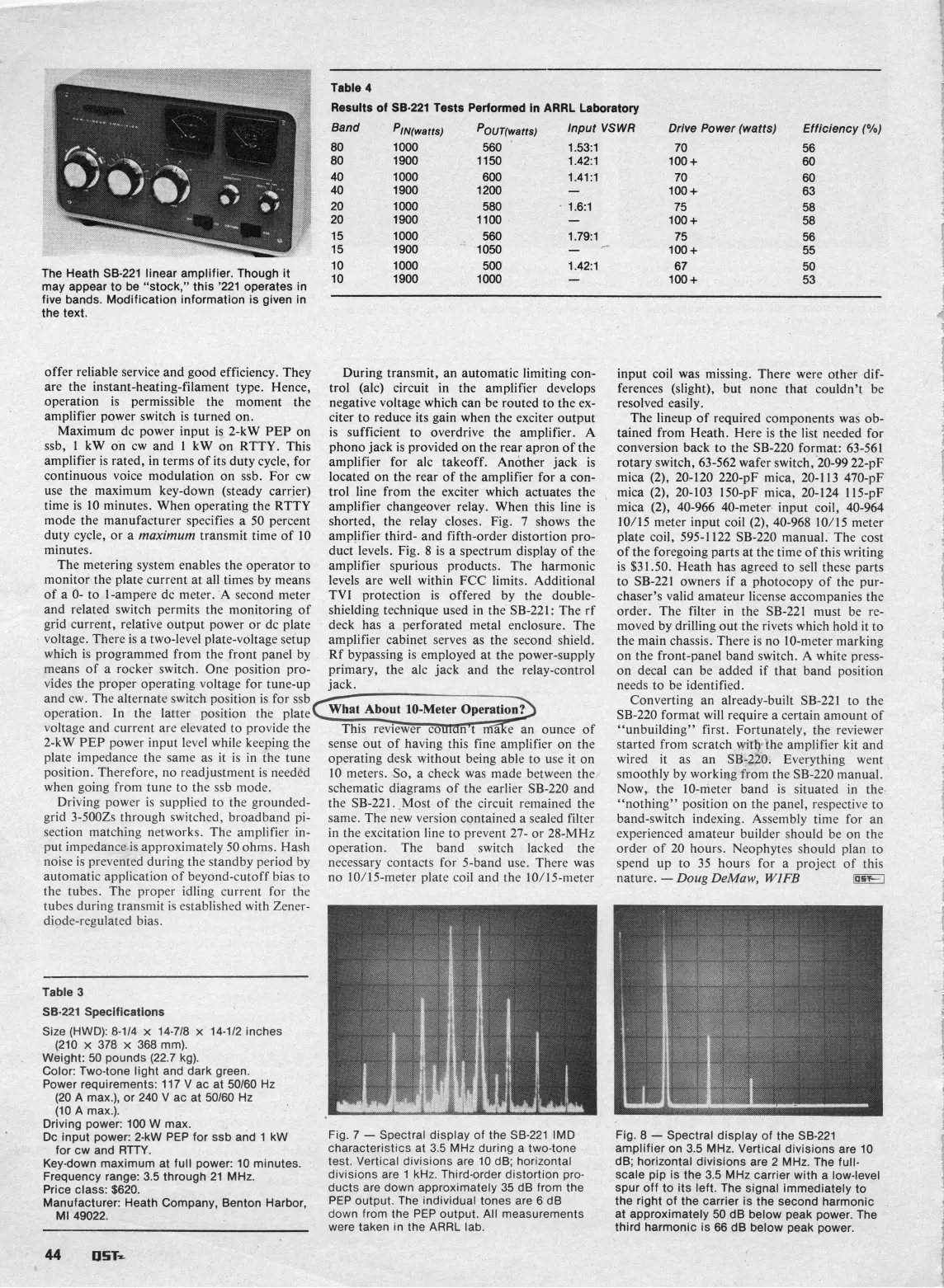
The Heath
SB-221
linear amplifier. Though it
1000 500
1.42:l 67 50
1900 1000
-
loo+ 53
may appear to be "stock," this
'221
operates in
five bands. Modification information
IS
given in
the text.
offer reliable service and good efficiency. They
During transmit, an automatic limiting con-
are the instant-heating-filament type. Hence, trol
(alc) circuit in the amplifier develops
operation is permissible the moment the negative voltage which can be routed to the
ex-
amplifier power switch is turned on. citer to reduce its gain when the exciter output
Maximum dc power input is
2-kW
PEP
on is sufficient to overdrive the amplifier. A
ssb, 1
kW on cw and 1 kW on RTTY. This
phono jack is provided on the rear apron of the
amplifier is rated, in terms of its duty cycle, for
amplifier for
alc takeoff. Another jack is
continuous voice modulation on ssb. For cw
located on the rear of the amplifier for a con-
use the maximum key-down (steady carrier)
trol line from the exciter which actuates the
time is 10 minutes. When operating the RTTY
amplifier changeover relay. When this line is
mode the manufacturer specifies a 50 percent
shorted, the relay closes. Fig.
7
shows the
duty cycle, or a
maximum
transmit time of 10
amplifier third- and fifth-order distortion pro-
minutes.
duct levels. Fig. 8 is a spectrum display of the
The metering system enables the operator to amplifier spurious products. The harmonic
monitor the plate current at all times by means
levels are well within FCC limits. Additional
of a
0- to I-ampere dc meter. A second meter TVI protection is offered by the double-
and related switch permits the monitoring of shielding technique used in the SB-221: The rf
grid current, relative output power or dc plate deck has a perforated metal enclosure. The
voltage. There is a two-level plate-voltage setup amplifier cabinet serves as the second shield.
which is programmed from the front panel by Rf bypassing is employed at the power-supply
means of a rocker switch. One position pro- primary,
the
alc jack and the relay-control
vides the proper operating voltage for tune-up jack.
and cw. The alternate switch position is for ssb
operation. In the latter position the plate
voltage and current are elevated to provide the
2-kW
PEP
power input level while keeping the
sense out of having this fine amplifier on the
plate impedance the same as it is in the tune
operating desk without being able to use it on
position. Therefore, no readjustment is needed
10 meters. So, a check was made between the
when going from tune to the ssb mode.
schematic diagrams of the earlier SB-220 and
Driving power is supplied to the grounded-
the SB-221. Most of the circuit remained the
grid
3-5002s through switched, broadband pi-
same. The new version contained a sealed filter
section matching networks. The amplifier in-
in the excitation line to prevent 27- or 28-MHz
put impedance is approximately 50 ohms. Hash operation. The band switch lacked the
noise is prevented during the standby period by necessary contacts for 5-band use. There was
automatic application of beyond-cutoff bias to no
10/15-meter plate coil and the 10/15-meter
the tubes. The Drover idline, current for the
input coil was missing. There were other dif-
ferences (slight), but none that couldn't be
resolved easily.
The lineup of required components was ob-
tained from Heath. Here is the list needed for
conversion back to the SB-220 format: 63-561
rotary switch, 63-562 wafer switch, 20-99
22-pF
mica (2), 20-120 220-pF mica, 20-113 470-pF
mica (2), 20-103 150-pF mica, 20-124 115-pF
mica (2), 40-966 40-meter input coil, 40-964
10115 meter input coil (2), 40-968 10/15 meter
plate coil, 595-1122 SB-220 manual. The cost
of the foregoing parts at the time of this writing
is $31.50. Heath has agreed to sell these parts
to SB-221 owners if a photocopy of the pur-
chaser's valid amateur license accompanies the
order. The filter in the SB-221 must be re-
moved by drilling out the rivets which hold it to
the main chassis. There is no
lo-meter marking
on the front-panel band switch. A white
press-
on decal can be added if that band position
needs to be identified.
Converting an already-built SB-221 to the
SB-220 format will require a certain amount of
"unbuilding" first. Fortunately, the reviewer
started from scratch with the amplifier kit and
wired it as an SB-220. Everything went
smoothly by working from the SB-220 manual.
Now, the 10-meter band is situated in the
"nothing" position on the panel, respective to
band-switch indexing. Assembly time for an
experienced amateur builder should be on the
order of 20 hours. Neophytes should plan to
spend up to 35 hours for a project of this
nature.
-Doug DeMaw,
WIFE
EK
tubcs during transm/t
i\
cstabkhcd with Zener-
diode-regulated bias.
Table
3
SB-221
Specifications
Size (HWD):
8-114
x
14-718
x
14-112
inches
(210
x
378
x
368
mm).
Weight:
50
pounds
(22.7
kg).
1
Color: Two-tone light and dark green.
Power requirements:
117
V
ac at
50160
Hz
(20
A max.), or
240
V
ac at
50160
Hz
(10
A max.).
Driving power:
100
W max.
Dc input power: 2-kW PEP for ssb and
1
kW
Fig.
7
-
Spectral display of the
SB-221
IMD
for cw and
RTTY.
characteristics at
3.5
MHz during a two-tone
Key-down maximum at full power:
10
minutes,
test. Vertical divisions are
10
dB; horizontal
Frequency range:
3.5
through
21
MHz.
divisions are
1
kHz. Third-order distortion pro-
Price class:
$620.
ducts are down approximately
35
dB from the
Manufacturer: Heath Company,
Benton Harbor,
PEP output. The individual tones are
6
dB
MI
49022.
down from the PEP output. All measurements
were taken in the ARRL lab.
Fig.
8
-
Spectral display of the
SB-221
amplifier on
3.5
MHz. Vertical divisions are
10
dB; horizontal divisions are
2
MHz. The fuil-
scale pip
is
the
3.5
MHz carrier with a low-level
spur off to its left. The signal immediately to
the right of the carrier
is
the second harmonic
at approximately
50
dB below peak power. The
third harmonic
is
66
dB below peak power.
 Loading...


