Upgrading Your
SB-220
Linear Amplifier
A
modest outlay for parts and a few hours on the workbench
. .
.
ingredients-for "customizing" this Heath workhorse. The
results will be longer life,
highel reliability and more operating
fl
In' "Upgrading the SB-220 Linear
convenience.
~rnplifier," February
1979
QsT,
R1
~hown in Fig.
1
has an effectiveresistance
By
Kenneth
M.
Gleszer,*
WIKAY
-
of
50
ohms, not 100 ohms as is indicated
L,
in the text. The 50-ohm value works
satisfactorily when the amplifier is being
COR~~"'
operated
011
117-V
house current, but on
234
V
ac a value of 200 ohms at
R1
pro-
vides better in-rush current control. It is
also necessary to use contacts
KlB for
both
117 V
aid 234
V
ac.
1
he continued popularity of the Heath
As a group, they seemed pleased
witrmwitch ivasmt to be desirable to enable
SB-220 linear amplifier after eight years in the unit's performance; however, most on-the-air tests and facilitate tune-up and
production is not surprising, considering
felt that there were a few areas that could band changing without constantly turning
its price and good reputation. Since
I
was
be improved upon. A few experienced the high-amperage 3-5002 filaments on
in the market for an amplifier
I
decided to
failure of one or more diodes in the high- and off. A few experienced what they felt
do a bit of research on the SB-220. I
voltage power supply. Many found the was premature failure of the now fairly
decided to ask some on-the-air questions cooling fan to be excessively noisy. Some expensive 3-5002 power tubes. Most
of present owners.
mentioned occasional arcing between the owners expressed the desire for a color
top inner shield of the case and the plate that would match equipment other than
*P.
0.
BOX
2234,
Stamford,
CT
06906
connections on the tubes. A STANDBY Heathkit.
As none of these problems seemed dif-
ficult to correct,
I
began by purchasing
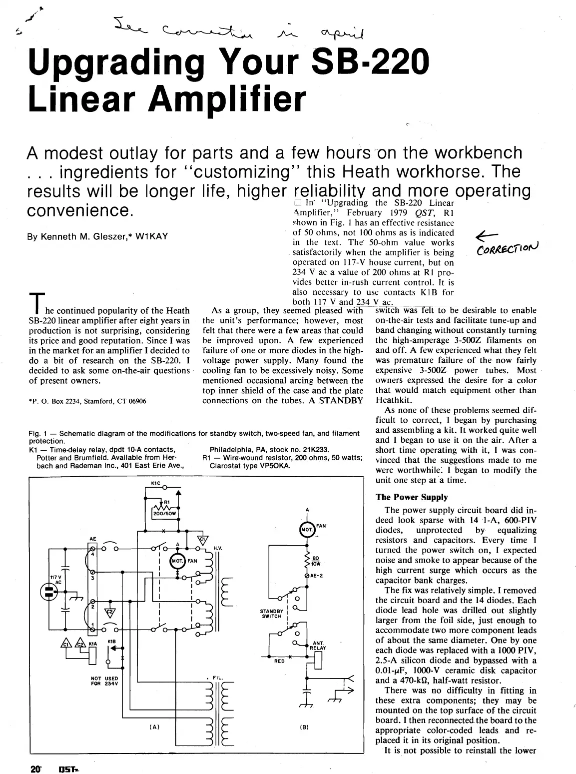
Fig
1
-
Schemat~c d~agrarn of the mod~f~cations for standby sw~tch, two-speed fan, and fllament
and
a
kit.
It
worked
quite
protect~on.
and
I
began to use it on the air. After a
K1
-
T~medelay relay, dpdt 10-A contacts, Ph~ladelph~a, PA, stock no. 21K233.
short time operating with it,
I
was con-
Potter and Brumf~eld. Available from Her-
R1
-
W~re-wound
resistor,
200 ohms, 50 watts;
,,inced that the suggeStions made
to
me
bach and Rademan Inc., 401 East Erie Ave.,
Clarostat type
VP50KA.
were worthwhile.
I
began to modify the
unit one step at a time.
The
Power
Supply
The power supply circuit board did in-
deed look sparse with 14
I-A,
600-PIV
diodes, unprotected by equalizing
resistors and capacitors. Every time
I
turned the power switch on,
I
expected
K1
C
r:"
AE-2
E
STANDBY
I
SWITCH
I
RELAY
FIL
aF
E
xJ+
(B)
noise and smoke to appear because of the
high current surge which occurs as the
capacitor bank charges.
The fix was relatively simple.
I
removed
the circuit board and the 14 diodes. Each
diode lead hole was drilled out slightly
larger from the foil side, just enough to
accommodate two more component leads
of about the same diameter. One by one
each diode was replaced with a
1000
PIV,
2.5-A silicon diode and bypassed with a
0.01-pF,
1000-V
ceramic disk capacitor
and a
470-kQ, half-watt resistor.
There was no difficulty in fitting in
these extra components; they may be
mounted on the top surface of the circuit
board.
I
then reconnected the board to the
appropriate color-coded leads and re-
placed it in its original position.
It is not possible to reinstall the lower