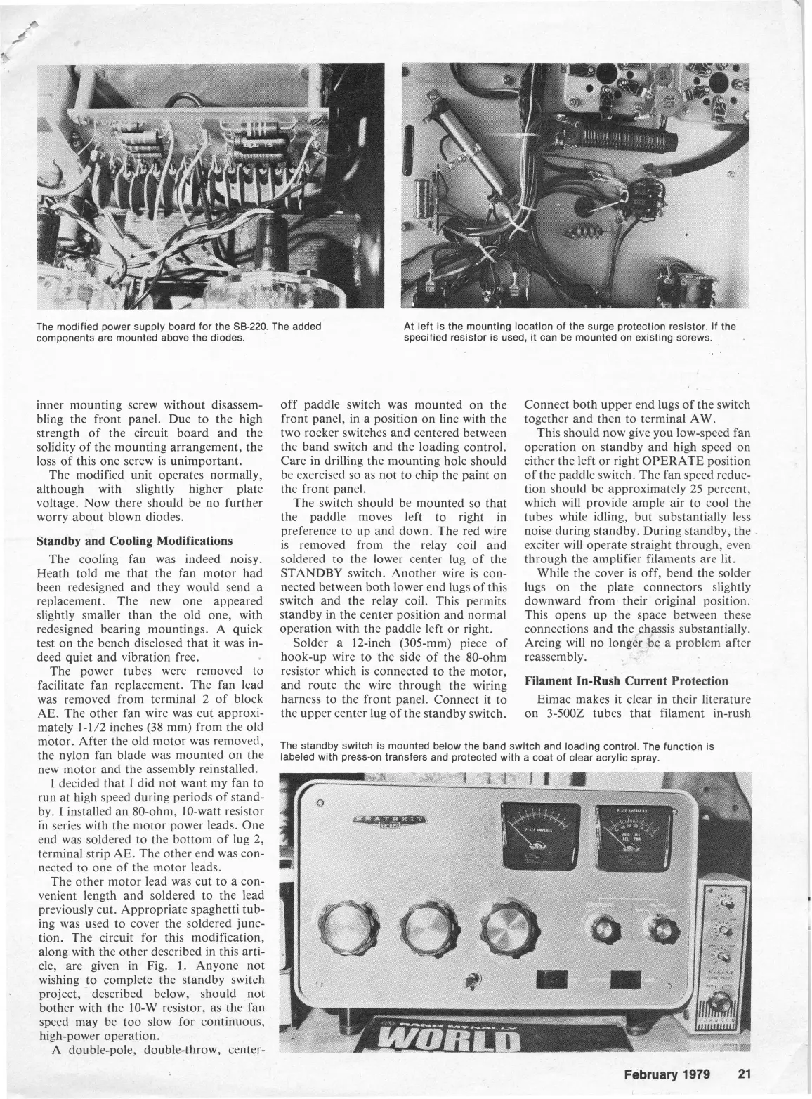
The modified power supply board for the SB-220. The added
components are mounted above the diodes.
inner mounting screw without disassem-
bling the front panel. Due to the high
strength of the circuit board and the
solidity of the mounting arrangement, the
loss of this one screw is unimportant.
The modified unit operates normally,
although with slightly higher plate
voltage. Now there should be no further
worry about blown diodes.
Standby and Cooling Modifications
The cooling fan was indeed noisy.
Heath told me that the fan motor had
been redesigned and they would send a
replacement. The new one appeared
slightly smaller than the old one, with
redesigned bearing mountings. A quick
test on the bench disclosed that it was in-
deed quiet and vibration free.
The power tubes were removed to
facilitate fan replacement. The fan lead
was removed from terminal
2
of block
AE.
The other fan wire was cut approxi-
mately 1-1/2 inches (38 mm) from the old
motor. After the old motor was removed,
the nylon fan blade was mounted on the
new motor and the assembly reinstalled.
I
decided that
I
did not want my fan to
run at high speed during periods of stand-
by.
I
installed an 80-ohm, 10-watt resistor
in series with the motor power leads. One
end was soldered to the bottom of lug 2,
terminal strip AE. The other end was con-
nected to one of the motor leads.
The other motor lead was cut to a con-
venient length and soldered to the lead
previously cut. Appropriate spaghetti tub-
ing was used to cover the soldered junc-
tion. The circuit for this modification,
along with the other described in this arti-
cle, are given in Fig. 1. Anyone not
wishing to complete the standby switch
-
project, described below, should not
bother with the 10-W resistor, as the fan
snoed may be too slow for continuous,
:h-power operation.
4
double-pole, double-throw, center-
At left is the mounting location of the surge protection resistor. If the
specified resistor is used, it can be mounted on existing screws.
.
off paddle switch was mounted on the
front panel, in a position on line with the
two rocker switches and centered between
the band switch and the loading control.
Care in drilling the mounting hole should
be exercised so as not to chip the paint on
the front panel.
The switch should be mounted so that
the paddle moves left to right in
preference to up and down. The red wire
is removed from the relay coil and
soldered to the lower center lug of the
STANDBY switch. Another wire is con-
nected between both lower end lugs of this
switch and the relay coil. This permits
standby in the center position and normal
operation with the paddle left or right.
Solder a 12-inch (305-mm) piece of
hook-up wire to the side of the 80-ohm
resistor which is connected to the motor,
and route the wire through the wiring
harness to the front panel. Connect it to
the upper center lug of the standby switch.
Connect both upper end lugs of the switch
together and then to terminal AW.
This should now give you low-speed fan
operation on standby and high speed on
either the left or right OPERATE position
of the paddle switch. The fan speed reduc-
tion should be approximately 25 percent,
which will provide ample air to cool the
tubes while idling, but substantially less
noise during standby. During standby, the
exciter will operate straight through, even
through the amplifier filaments are lit.
While the cover is off, bend the solder
lugs on the plate connectors slightly
downward from their original position.
This opens up the space between these
connections and the chassis substantially.
Arcing will no longer be a problem after
reassembly.
Filament In-Rush Current Protection
Eimac makes it clear in their literature
on
3-5002 tubes that filament in-rush
The standby switch is mounted below the band switch and loading control. The function is
labeled with press-on transfers and protected with a coat of clear acrylic spray.
February
1979 21