1
an open-ended chassis equipped with a
1
'
single, 6-inch-diameter fan blade that could
I
simultaneously blow cooling air above and
below the chassis.
I
To position the four hot filament pins
optimally in the under-chassis airflow, the
1
pair of tube sockets was mounted with the
I
two pairs of filament pins facing each
other. This optimally positions the hottest
1
parts in front of the tips of the fan blades.
I
The cooling-system design is brilliantly
simple. It's relatively quiet and works well.
1
Reports of tube-pin solder melting in
I
SB-220 amplifiers are very rare (with the
exception of cases where the fan-motor
1
bearings seized because they were never
I
oiled!). On the other hand,
I
have heard
of many 3-500Z-pin solder-melting
epi-
I
sodes in other amplifiers that used centri-
fugal blowers and air-system-chimney
1
cooling.
I
One weakness in the SB-220's cooling
system is that the infrared radiation (heat)
1
reflected back into the tubes from the
I
bright aluminum surfaces adjacent and
parallel to the anodes shortens tube life.
I
This deficiency is easily corrected: After
removing the tubes, apply black liquid shoe
polish to the vertical aluminum surfaces
near the tubes.
Fan Oiling
An oversight in early SB-220s was the
failure to provide oil holes for the
fan-
motor bearings. This problem can be cor-
rected by drilling a small hole, no more
than
1/4
inch deep, above the front and rear
bearings. It's not necessary to remove the
fan motor to do this. The fan should be
lubricated at least annually with a thin,
non-gumming
oil such as Hoppe's
no.
1003.4.5 Insert a drop or two of such
oil into each hole. What isn't absorbed by
the felt wicks that surround the bearings
simply dribbles out.
More oil is not better,
just messier.
The easiest way to get the
desired amount of oil in the holes is to
apply the oil with a disposable insulin
syringe (available at most drug stores); each
unit on such a syringe is equivalent to
approximately one drop of oil.
Premature Filter-Capacitor Failure
Aluminum-electrolytic filter capacitors
are very sensitive to heat. For every
10-"C
increase above room temperature, capaci-
tor life expectancy is approximately
halved.
The electrolytic filter capacitors in the
SB-220 are subjected to high heat during
normal operation, mostly because of their
proximity to their eight associated 30-kfl
voltage-equalizing/bleeder
resistors. During
transmit, another (minor) source of capa-
citor heating is the 60-Hz ripple current
flowing through each capacitor.
The capacitor-heating problem is com-
pounded because cooling air does not reach
the capacitors. In some cases, the heat
present partially melts the ends of the capa-
citor holders that are nearest to the 30-kfl
resistors!
Heat dissipated by these resistors can be
reduced by about 70% by replacing them
with
100-kQ, 2- or 3-W, 5%-tolerance film
resistors. Other resistance values may be
used, up to roughly 150
kfl, provided that
the resistors are rated to withstand the volt-
age applied to them and the resistor values
are within 5% of each other. I do not
recommend using ancient 2-W
carbon-
composition resistors for this application.
They don't stay within their rated tolerance
as
they age. This simple modification greatly
prolongs the life of the electrolytic filter
capacitors.
Note: Increasing the equalizing-resistor
values also increases the capacitor
bleed-
down time after the amplifier is shut off.
Because this amplifier has a shorting HV
interlock that grounds the HV-positive lead
when the cover is removed, it's advisable
to wait until the front-panel voltmeter
indicates nearly
0
V before allowing the
interlock to short the
HV
line to the chas-
sis. Here's why: When the HV positive
is shorted to ground, the energy stored in
the filter capacitors is applied
directly
to
the grid-current-meter shunt resistor, R3
(0.82
Q),
which is the only HV-negative
path to chassis. The peak discharge current
can be substantial, and damage to the meter
shunt and movement can occur.
For example, if the filter-capacitors are
at the 100-V level when the interlock shorts,
the peak current through R3 is
100 V/
0.82 fl
=
>
I00
A.
If a substantial voltage
exists in the filter capacitors when the in-
terlock shorts, R3 can be literally
blown
away
by the discharge-current pulse! If the
multirneter happens to be in the grid-current
position, the meter can also be
crispy-
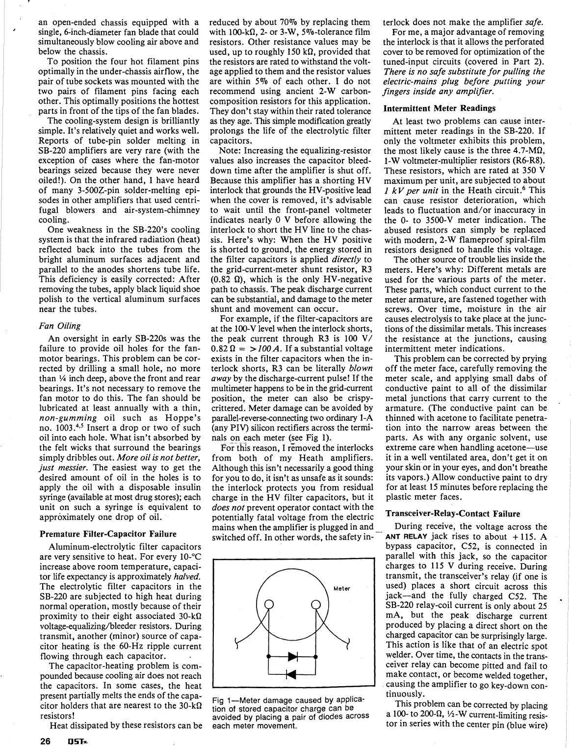
crittered. Meter damage can be avoided by
parallel-reverse-connecting two ordinary 1-A
(any
PIV)
silicon rectifiers across the termi-
nals on each meter (see Fig 1).
or
this reason, I removed the interlocks
from both of my Heath amplifiers.
Although this isn't necessarily a good thing
for you to do, it isn't as unsafe
as
it sounds:
the interlock protects you from residual
charge in the HV filter capacitors, but it
does not
prevent operator contact with the
potentially fatal voltage from the electric
mains when the amplifier is plugged in and
switched off. In other words, the safety
in-
Fig
1
-Meter damage caused by applica-
tion of stored capacitor charge can be
avoided
by
placing a pair of diodes across
each meter movement.
terlock does not make the amplifier
safe.
For me, a major advantage of removing
the interlock is that it allows the perforated
cover to be removed for optimization of the
tuned-input circuits (covered in Part 2).
There is no safe substitute for pulling the
electric-mains plug before putting your
fingers inside any amplifier.
Intermittent Meter Readings
At least two problems can cause inter-
mittent meter readings in the SB-220. If
only the voltmeter exhibits this problem,
the most likely cause is the three 4.7-Mfl,
1-W voltmeter-multiplier resistors (R6-R8).
These resistors, which are rated at 350 V
maximum per unit, are subjected to about
1
kVper unit
in the Heath circ~it.~ This
can cause resistor deterioration, which
leads to fluctuation and/or inaccuracy in
the 0- to
3500-V meter indication. The
abused resistors can simply be replaced
with modern, 2-W flameproof spiral-film
resistors designed to handle this voltage.
The other source of trouble lies inside the
meters. Here's why: Different metals are
used for the various parts of the meter.
These parts, which conduct current to the
meter armature, are fastened together with
screws. Over time, moisture in the air
causes electrolysis to take place at the junc-
tions of the dissimilar metals. This increases
the resistance at the junctions, causing
intermittent meter indications.
This problem can be corrected by prying
off the meter face, carefully removing the
meter scale, and applying small dabs of
conductive paint to all of the dissimilar
metal junctions that carry current to the
,
armature. (The conductive paint can be
thinned with acetone to facilitate penetra-
tion into the narrow areas between the
parts. As with any organic solvent, use
extreme care when handling acetone-use
it in a well ventilated area, don't get it on
your skin or in your eyes, and don't breathe
its vapors.) Allow conductive paint to dry
for at least 15 minutes before replacing the
plastic meter faces.
Transceiver-Relay-Contact Failure
-
During receive, the voltage across the
ANT
RELAY
jack rises to about
+
115. A
bypass capacitor, C52, is connected in
parallel with this jack, so the capacitor
charges to 115 V during receive. During
transmit, the transceiver's relay (if one is
used) places a short circuit across this
jack-and the fully charged C52. The
.
SB-220 relay-coil current is only about 25
mA, but the peak discharge current
produced by placing a direct short on the
charged capacitor can be surprisingly large.
This action is like that of
an electric spot
welder. Over time, the contacts in the trans-
ceiver
relay can become pitted and fail to
make contact, or become welded together,
causing the amplifier to go key-down con-
tinuously.
This problem can be corrected
by placing
a
100-
to 200-fl,
!h-W
current-limiting resis-
tor in series with the center
pin (blue wire)
 Loading...


