to
K1
Coil.
Fig
2
loo-
200
n
C52
0.02
pF
ANT
RELAY
Fig 2-Transceiver-relay-contact pitting and
eventual failure can result from use with
the
TR
switching circuit
in
the SB-220.
Adding a 100- to 200-Q,
%-W
resistor to
the circuit as shown eliminates this trouble
spot. All part numbers are those used
by
Heath.
on the antenna-relay jack.
C52 must be
connected to the blue-wire end of the resis-
tor. See Fig 2. The drop across this resis-
tor will be only about 5 V, which is
insignificant to the 110-V relay coil.
The Filament Circuit
The most popular published modifica-
tion for the SB-220 has been
filament-
inrush-current limiting. A large number of
3-500Zs in SB-220s suffered from filament
to-grid shorts, so some people began to
theorize that excessive filament-inrush cur-
rent was the villain. Another theory was
that the filament-to-grid shorts were caused
by a manufacturing defect. Neither theory
turned out to be true.
Curiously, none of the authors who
wrote the SB-220 inrush-current-limiting
articles published measured filament-inrush
current. So, I decided to measure it with
my HP
1706A oscilloscope. (After all, my
name is Measures, so why not?)
Here's what
I
found: The maximum
inrush current through the
3-5002 fila-
ments in an SB-220 is only 60% of what
Eimac allows. Heath accomplished this
esoteric feat by the use of a special
current-
limiting core in the SB-220's filament trans-
former. The core is similar to those used
in current-limiting neon-sign transformers.
Externally, this core appears to be substan-
tially different than the core used in the HV
transformer.
The cause of
virtually
all
grid-to-filament
shorts in the
3-5002s
was
later discovered
to be a very brief, and usually very noisy,
parasitic oscillation at roughly 110
MHz.'
As will be discussed later, the large grid-
current pulse that accompanies this oscil-
lation creates a large electromagnetic pulse
inside the
3-500Zs, pulling the hot filament
wires off center, causing them to touch the
grid cage.
Another interesting feature concerning
the SB-220 filament circuit is that it nor-
mally operates near the low end of the
recommended 3-5002 filament-voltage
range; typically about 4.85 V (the recom-
mended range is 4.75 to 5.25 V). This may
not seem important, but according to
Eimac, each 3% reduction in filament volt-
age (with no drop in PEP output)
doubles
the life expectancy of a 3-5002. Thus, all
other things being equal, the tubes in an
SB-220 can be expected to last at least four
times longer than the tubes in some other
3-5002 amplifiers.
For example, another (much more
expensi~e)~ 2
x
3-5002 amplifier that is
considered by some to be a better designed,
higher-output and more rugged amplifier
than the SB-220 has a filament potential of
more than 5.90 V at an ac-line supply of
240 V. This clearly exceeds the 3-5002's
maximum-filament-voltage rating, and
reduces the useful emission life of the two
3-5002s to only a few percent of what could
have been realized if the tubes had been
operated near the low end of the recom-
mended filament-voltage range.
Although the filament circuit in the
SB-220 needs no step-start circuit to pro-
tect the tubes from high filament-inrush
current, there is another good reason to add
such a circuit to the SB-220. If the ampli-
fier is turned on in the SSB mode, when
powered by stiff, 240-V ac mains, the
inrush current through the power switch
and other components is considerable. A
step-start circuit will eliminate this poten-
tial source of trouble. (If an SB-220 is
always
started up in the
CWiTUNE
mode,
and then switched to
SSB,
the inrush cur-
rent is lower, and a step-start circuit is
probably not needed.)
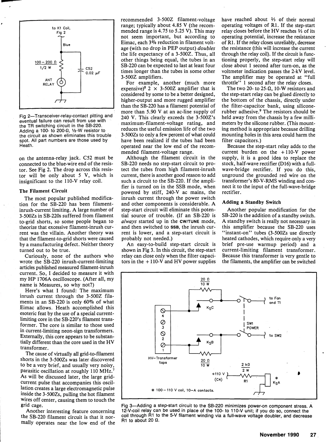
An easy-to-build step-start circuit is
shown
in
Fig 3. In this circuit, the step-start
relay can close only when the filter capaci-
tors in the
+
110-V and HV power supplies
have reached about
%
of their normal
operating voltages of
R1. If the step-start
relay closes before the HV reaches
%
of its
operating potential, increase the resistance
of
R1. If the relay closes unreliably, decrease
the resistance (this will increase the current
through the relay coil). If the circuit is func-
tioning properly, the step-start relay will
close about 1 second after turn-on,
as
the
voltmeter indication passes the
2-kV level.
The amplifier may be operated at "full
throttle" 1 second after the relay closes.
The two 20- to
254, 10-W resistors and
the step-start relay can be glued directly to
the bottom of the chassis, directly under
the filter-capacitor bank, using
silicone-
rubber adhe~ive.~ The resistors should be
held away from the chassis by a few milli-
meters by the silicone rubber. (This mount-
ing method is appropriate because drilling
mounting holes in this area could harm the
filter capacitors.)
Because the step-start relay adds to the
current burden on the
+
110-V power
supply, it is a good idea to replace the
stock, half-wave rectifier
(D16) with a full-
wave-bridge rectifier. If you do this,
unground the grounded red wire on the
transformer's 80-V-RMS winding and con-
nect it to the input of the full-wave-bridge
rectifier.
Adding a Standby Switch
Another popular modification for the
SB-220 is the addition of a standby switch.
A standby switch is really not necessary in
this amplifier because the SB-220 uses
"instant-on" tubes
(3-5002s use directly
heated cathodes, which require only a very
brief pre-use
warmup period) and a
current-limiting filament transformer.
Because this transformer is very gentle to
the filaments, the amplifier can be switched
Fig 3-Adding a step-start circuit to the SB-220 minimizes power-on component stress.
A
12-V-coil relay can be used
in
place of the 100- to 110-V unit;
if
you do so, connect the
coil through
R1 to the
5-V
filament winding via a full-wave voltage doubler, and decrease
R1
to about
20
0.
20
n
-
10
W
"
-
0-
:R
I
4
I
0
I
I
November
1990
27
3
8
2
0
1
SW1
h
0%
to
SW2
HV-Tronsformer
taps
20
n
-
2
kn
10
W
-
+IIO
v
8
*
100-
110
V
coil,
10-A
contacts.