7
RECEIVER LOCATION
Select a position for the receiver that provides
protection from violent impact from debris or thrown
materials and is easily accessible. The receiver
housing is rated IP65 and can withstand direct water jet
spray and is protected against penetration of dust.
There are different sizes and types of receiver
housings. All receivers must be free from metal
obstructions on at least 3 sides with the antenna
pointing straight up.
• Depending on customer specification, the
receiver can be operated with AC, DC or both.
• Receiver must be protected from corrosive gases
or liquids
• Receiver must be protected from ambient
temperatures outside the range of -18
º to 158º F
(-25
º to +75º C)
Receiver Production Number
Locate the Hetronic Production number decal on the
receiver housing. This number is required when
Hetronic is called for any service or parts information.
Be sure the decal is easily accessible when the
receiver is mounted to the equipment. Please make a
note of the Production and System numbers in the
boxes provided in the Introduction Section of this
manual.
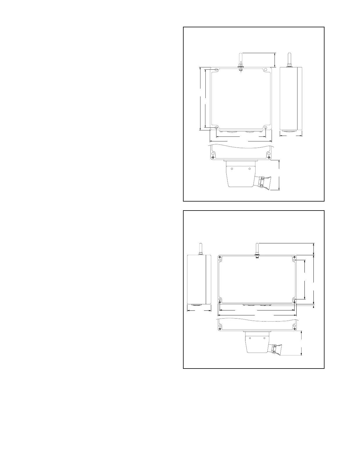
MOUNTING THE RECEIVER
1. Determine the receiver position.
2. If the receiver is to be mounted inside a control
panel or other enclosure, an external antenna is
required.
3. Be sure there is clearance for connectors and
components that need to be wired.
4. Drill holes into the mounting surface according to
the dimensions shown.
NOTE: Receiver housing dimensions are molded into
the back surface of the housing.
5. Remove the cover from the receiver housing (if
necessary).
6. Insert the mounting screws through the holes in
the receiver housing and tighten into the
mounting surface.
7. Please refer to the appropriate illustration for
mounting dimensions. Contact Hetronic for more
information or if you have questions.
8. Lay out the wire runs. Use #16 AWG (size 1.5
mm
2
metric) minimum for power wiring.
9. If the receiver includes an attached antenna,
mount the receiver so that the antenna points
straight up. The area around the antenna should
be free of obstructions, especially metal.
250.0
(10.00)
236.0
(9.44)
250.0 (10.00)
200.5 (8.02)
120.0
(4.80)
125
(5.00)
60
(2.38)
mm (in)
Antenna must be vertical
(pointing up).
Area must be free of
obstructions
Optional Quick-Disconnect Plug
250 x 250 Receiver
236
(9.44)
381.5 (15.25)
400 (16.00)
120
(4.80)
250
(10.00)
60
(2.38)
mm (in)
8 mm
125
(5.00)
Antenna must be vertical
(pointing up).
Area must be free of
obstructions
Optional Quick-Disconnect Plug
250 x 400 Receiver