CP : control panel, FC : frequency converter, SB : supply board, CB : cooling board, CC : control cable, LL : lid locking, BC : braking chopper,
BR : brake resistor, MR : mains reset, EC : error cause, ES : error consequence, ER : error remedy, M : measurements, ECR : error-code reset
31/51
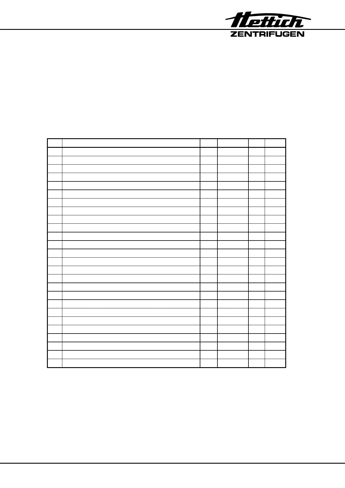
In Table 9-A the components are ordered in the following sequence:
Column 1: Abbreviation
Column 2: Components
Column 3: Abbreviations in the circuit diagrams
Column 4: Plug connections
Column 5: Connections at the electronic-panels
Column 6: Described in capture.
Table 9-A
1 2 3 4 5 6
A Speed sensor (speedometer) B3 X4 A1 9.1
B Motor M1 S101 A2 9.2
C Vibration damper 9.2
D FC (frequency converter) A2 9.3
E EPROM (on FC) A2 9.3
F SB (supply board) A1 9.4
G CB (cooling board) A3 9.5
H CP (control panel) A4 9.6
I EPROM (on CP) A4 9.7
J Mains choke coil - 9.12
K CC (control cables) - 16 conductors A4-A1 9.8
- 10 conductors A1-A2
- 10 conductors A4-A3
L LL (lid locking) Y1 X5 A1 9.9
M BR (brake resistor) R1 P10-P1 A2 9.10
N Radio interference suppression filter Z1 X5-Q1 A1 9.11
O Mains switch ON / OFF Q1 Z1-F1 9.13
P Appliance plug B4 F1 9.14
Q Overvoltage protection F1 B4-Q1 9.14
R Imbalance switch S1 X3 A1 9.15
T Temperature sensor (centrifuge chamber) B1 X3 A3 9.16
U Temperature sensor (condenser) B2 X2 A3 9.17
V Fan (compressor) M3 X1 A3 9.18
W Compressor M2 X1 A3 9.19
X Lid spring 9.20
Y Hinge block 9.21