July 2016 Page 7 of 25
see
VertX EVO V1000 User Guide, 71000-901, Rev. A.4
3 Connect
3.1 What you need before getting started
Prior to starting the installation, completely read this guide.
See Section Appendix C: Configuration Checklist - Static, and gather the information before
proceeding with these instructions.
CAUTION: VertX controllers and panels are sensitive to Electrostatic Discharges (ESD).
Observe precautions while handling the circuit board assembly by using proper grounding
straps and handling precautions at all times.
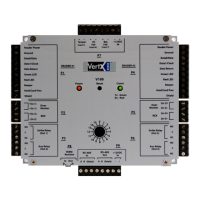
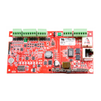
3.2 V1000
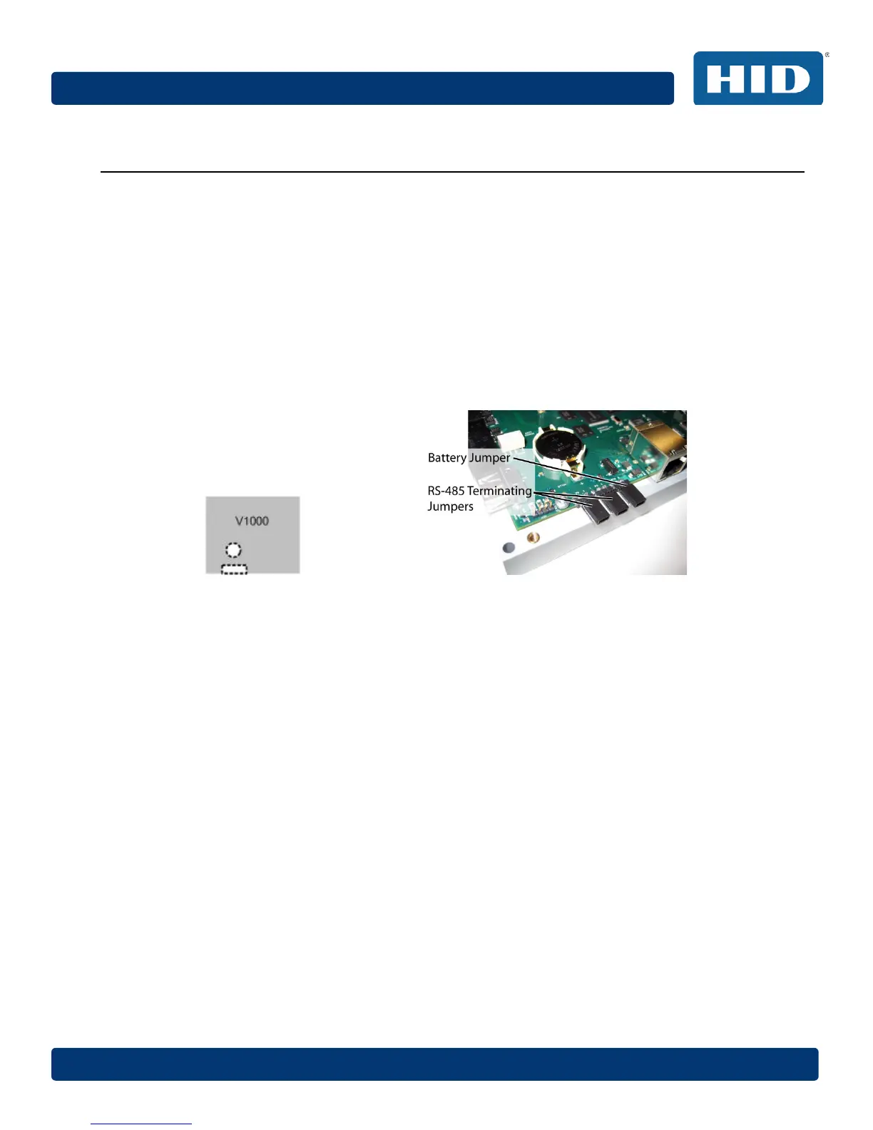
1. Verify the battery jumper is installed in the ON position, P10 connector.
2. If installing a V1000 - Verify the RS-485 termination jumper is in the Out position
when there are no panels attached to the port. If there are downstream interface
panels attached, place the termination jumper in the In position. The V1000 is
shipped with jumpers in the Out positions.
Note: P6 controls Port 2 and P5 controls Port 1. This is an issue if one of the jumpers
is in the IN position and the other is in the OUT position.
3.3 Mounting Instructions
1. Always mount the controllers and interface panels in a secure area.
2. Mount using the four mounting screws (provided) or other appropriate fasteners.
Place the fasteners in the corner holes of the base.
3. Stack the VertX EVO devices with or without the cover. Do not remove the plastic
base. Position the VertX EVO devices in such a way as to provide room for wiring, air-
flow and cable runs.
CAUTION: Stacking the VertX EVO devices without the cover in place risks the danger of
breaking the LEDS unless spacers are used for separation.