2. Wiring and connection
2-11
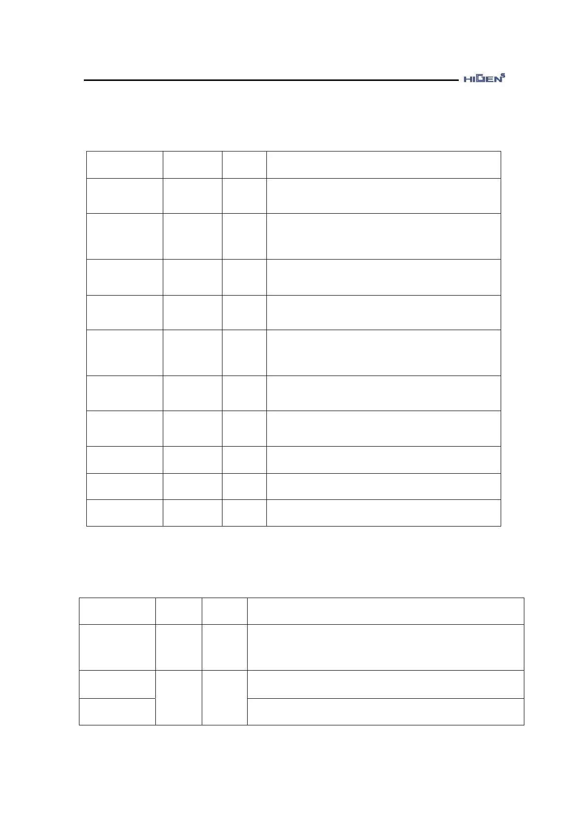
2.3.4 Variable output signal function table (Based on manufactured default)
Signal content Name
Pin
number
Function and usage explanation
- - 23
You can directly set the input contact point function
from P7-01. (Manufactured default : Not use)
Brake
operation
BRAKE 48
This is the output signal to operate the external
brake.
When on, the brake power is supplied to enable
motor operation.
Servo ready RDY 21
No alarm, power good condition when the power is
on.
Speed/Position
/Torque reach
completion
INSPD/INP
OS/INTRQ
22
It goes on when it reaches the commanded
Speed/Position/Torque.
Speed/torque
limiting
SPDOUT/
TRQOUT
46
When used for speed control mode, it indicates the
condition of the torque the servo motor is limiting.
When used for torque control mode, it indicates the
condition of the speed the servo motor is limiting.
Zero speed
condition
ZSPD 47
This indicates the stopped condition of the servo
motor.
Alarm
condition
ALARM 20
When the alarm is detected, it foes off. During
normal operation, it goes on.
Alarm 0 CODE A_CODE0 45 It outputs alarm CODE0.
Alarm 1 CODE A_CODE1 19 It outputs alarm CODE1.
Alarm 2 CODE A_CODE2 44 It outputs alarm CODE2.
♥ For details on the output contact point function change, refer to the P08 mode of Chapter 3.
2.3.5 Fixed I/O signal function table
Signal content Name
Pin
number
Function and usage explanation
F+ input pulse
F- input pulse
R+ input pulse
R- input pulse
PPFIN
PFIN
PPRIN
PRIN
11
10
9
12
Depending on the set value of pulse logic, it receives and
operates according to the specific position command type of
negative or positive logic. Refer to Chapter 3 for details of
the pulse type.
Analog speed
command
When operating in speed mode, enter the analog speed
command.
Analog speed
limit
SPDIN 27
When operating in torque mode, enter the analog speed
limit.