2. Wiring and connection
2-15
11 /PZ 6 F
F.G. 8 N
12
Shield 15 J
13 /PB 4 D
14 PZ 5 E
15 /PA 2 B
16 PB 3 C
17
18 PA 1 A
19 Vcc( DC 5V ) 13 H
20 ERST 7 M
♥ Connect the grounding wire of the encoder wiring cable for F.G
♥ Applied cable specification: AWG24 x 9Pair TWIST,SHIELD CABLE (Maximum length 20m)
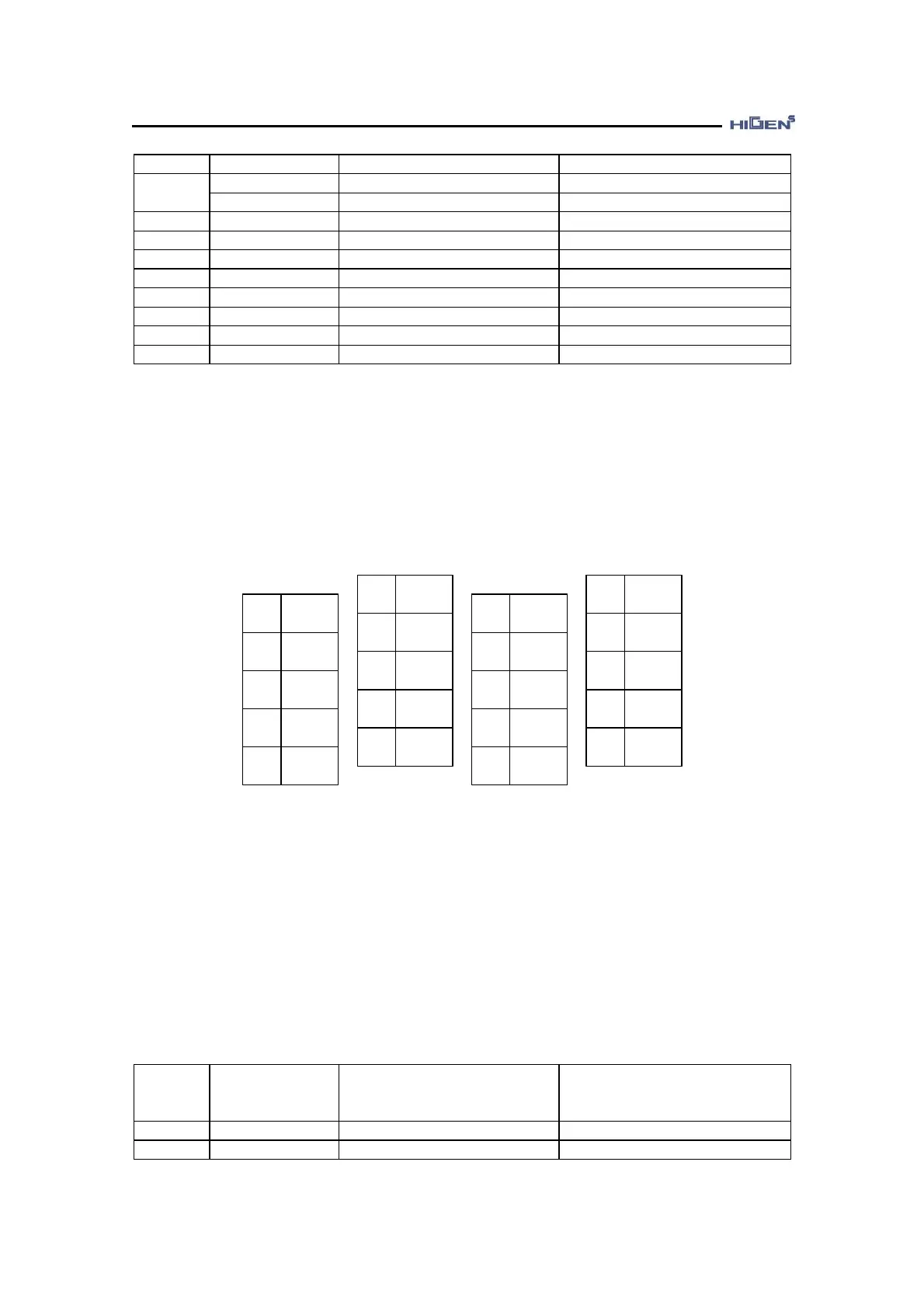
2.4.3 17bit absolute/incremental encoder
2 /SD
4
6
8 BT-
10
1 SD
3
5
7 BT+
9 GND
12
FG
/Shield
14
16
18
20
11
13
15
17
19 Vcc
[ Based on soldering side of user connector ]
◆ The connector for CN2 is optional.
◆ For incremental 17bit encoder, you do not need to connect the No. 7 (BT+) and No. 8 (BT-)
terminal.
- Manufacturer : 3M, CASE product name : 10320-52F0-008,
- Connector (for soldering) : 10120-3000VE
The 17bit absolute encoder wiring details of CN2 and FMA-series AC servo motor are shown
as the following table.
CN2
PIN No.
(Drive)
Signal name
(Drive)
MOTOR(□60,80 series) side
Connector pin no. for
encoder
MOTOR(□130,180 series)
side
Connector pin no. for encoder
1 SD 1 P
2 /SD 2 R