5. Servo operating
4-2
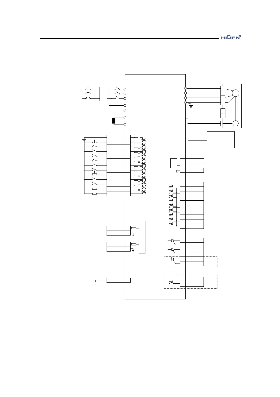
4.1.1. CN1 wiring diagram for speed control servo
Servo Drive
FDA7000
R
S
T
r
t
P
B
CN1
(INPUT)
49
39
43
17
42
16
13
18
38
14
41
40
15
27
28
3.3K
+
-
+24V
U
V
W
FG
SM
+
-
Brake
Input Voltage
Terminal
U
V
W
FG
PG
CN2
CN3
3
2
22
48
21
47
46
20
45
19
44
7
32
6
31
5
30
CN1
(OUTPUT)
A/D
D/A
NF
Input Voltage
FDA7000 Type : AC220V
FDA7000-H0 Type : AC380V
FDA7000-H1 Type : AC440V
50/60Hz
NFB MC1
Regenerative
Resistance
*PC Loader(RS232C)
*Network communication
(RS485, RS232C)
(Note1)
(Note2)
50
(Note4)
(Note3)
3.3K
3.3K
3.3K
3.3K
3.3K
3.3K
3.3K
3.3K
3.3K
3.3K
3.3K
LPF
LPF
23
(Note5)
(Note6)
1
33
34
36
24
25
8
26
24
25
+24V
ESTOP
SPD1/GEAR1
SPD2/GEAR2
SPD3
DIR
STOP
SVONEN
ALMRST
SPDLIM/TLIM
PI/P
CWLIM/
NTQLIM
CCWLIM/
PTQLIM
SPDIN
GND
TRQIN
GND
FG
MONIT1
MONIT2
GND
INSPD/INPOS
/INTRQ
BRAKE
RDY
ZSPD
SPDOUT/
TRQOUT
ALARM
A_CODE0
A_CODE1
A_CODE2
GND24
PAO
/PAO
PBO
/PBO
PZO
/PZO
OPC_ZO
GND24
♥ The above input and output contact points are shown when setting the speed control mode contact point.
(P07-01,P08-01=26).
(Note1) Be sure to use Noise Filter (NF) to prevent noise from entering the outside.
(Note2) Supply power to the r and t terminals as shown below.
FDA7004-H1 ~ FDA7150-H0 : AC 220V
FDA7020-H0 ~ FDA7750-H0 : AC 380V
FDA7020-H1 ~ FDA7750-H1 : AC 440V