Do you have a question about the HikRobot VB2200 Series and is the answer not in the manual?
Provides instructions for using and managing the product, subject to change.
Lists Hikrobot's trademarks and logos, and those of other companies like HDMI.
Limits Hikrobot's liability for product use, data security, and legal compliance.
Details FCC compliance for digital devices, limits on interference.
Specifies the two conditions for FCC compliance: no harmful interference, accepting received interference.
States product marks like "CE" and compliance with European standards (EMC, LVD, RoHS).
Defines symbols used in the manual (NOTE, WARNING, DANGER) and their meanings.
States the manual applies to the VB2200 Series Vision Box.
General instructions to ensure correct product use and prevent danger or loss.
Emphasizes use in compliance with local laws and safety regulations.
Instructions for safe power supply connection and operation, avoiding electrification.
Guidelines for safely transporting the product, avoiding pressure and vibration.
Specifies suitable and unsuitable environmental conditions for product operation and storage.
Details measures to prevent damage from static electricity during handling and installation.
Instructions for product maintenance, advising against disassembly and recommending contacting service centers.
Advises against installing the product on vibrating or impact-prone surfaces.
Outlines qualifications, knowledge, and skills needed for installation and maintenance personnel.
Provides company address, email, and website for support.
Provides steps for reinstalling the device's operating system via BIOS.
Offers solutions for common issues like no VGA interface, blank screen, or IP address problems.
Introduces the VB2200 series vision box, its processor, and applications.
Lists the main features of the VB2200 series vision box, including CPU, memory, interfaces, and design.
Provides the physical dimensions of the vision box with a diagram.
Describes how to install and fix the vision box on a mounting plate and other parts.
Explains how to access the device remotely via PC and default credentials.
Lists recommended accessories for the vision box, including power adapter, cables, and mounting plate.
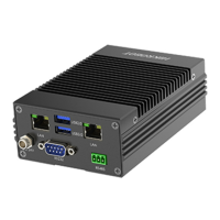
Identifies and labels the various indicators and interfaces on the vision box panel.
Details the 11-pin GPIO interface, including pin definitions and input/output types.
Explains voltage ranges for opto-isolated inputs and connection modes (PNP/NPN).
Details voltage ranges for opto-isolated outputs and current limitations.
Describes the built-in USB interface for expanded connectivity, noting it's disabled by default.
Details the standard D-sub 9-pin RS-232 communication interface and its pin definitions.
Describes the differential half-duplex RS-485 interface and its pin definitions.
Explains the 2 HDMI interfaces for monitor connection and alternative VGA connection.
Introduces the IO controller interface for managing GPIO and light source settings.
Guides on checking COM port and IRQ information via Device Manager.
Details how to configure serial port settings like baud rate and parity for connection.
Covers input signal detection and configuration settings.
Explains how to detect and interpret input signal levels (high/low) using color indicators.
Describes configuring input settings like trigger signal, delay, and debouncer time.
Covers output settings and enabling output signals.
Details setting output parameters like mode, electrical level, duration, and pulse.
Explains how to enable or disable device output signals for ports.
Describes setting up connections between input and output interfaces for signal flow.
Guides on adjusting light source parameters like status (On/Off) and brightness.
Explains how to view, clear, or save real-time messages from the device.
Describes enabling edge detection to view input edge signals and their quantity.
Instructs on how to upgrade the device's firmware.
The VB2200 Series Vision Box is a control system designed for machine vision applications, integrating various interfaces and featuring stable performance, a compact structure, and fast response. It is widely applicable in robotics, laser equipment, numerical control machine tools, and package testing.
The vision box serves as a central control unit, processing image data and managing peripheral interactions. It is equipped with multiple interfaces to facilitate its role in complex machine vision setups. The device supports both opto-isolated inputs and outputs, allowing for robust and reliable communication with external devices in industrial environments. The opto-isolated input system is designed to handle different electrical level types, with a high electrical level input ranging from 10 V to 30 V and a low electrical level input from 0 V to 2 V. This flexibility ensures compatibility with various external sensors and triggers. The input system is specifically designed for NPN opto-isolated input, requiring different connection modes depending on the electrical characteristics of the connected devices sending signals (PNP or NPN external devices).
Similarly, the opto-isolated output system uses an open collector and unidirectional output, where current from an external power supply flows into and out of the opto-isolated output port. Each output pin can handle a current of up to 90 mA. The output channels support a high electrical level output from 5 V to 30 V and a low electrical level output from 0 V to 1.1 V. Like the input, the output system is NPN opto-isolated, necessitating specific connection modes for different connected devices receiving signals.
The device also features multiple communication ports, including RS-232 and RS-485 interfaces, which are crucial for serial communication with other industrial equipment. The RS-232 interface is a standard D-sub 9-pin connection, while the RS-485 interface provides a differential half-duplex connection, enabling robust data transmission over longer distances and in noisy environments.
For visual feedback and display, the vision box includes two independent HDMI video outputs, supporting a maximum resolution of 2560 x 1600. This allows for connection to high-resolution monitors, and if a monitor only supports VGA, an HDMI-to-VGA cable or device can be used.
A built-in USB interface is also available for expanding connectivity, such as for dongle installation or other fixed USB devices, preventing accidental disconnections. This feature is disabled by default and requires notification during the order process if needed, along with the removal of the device case for cable installation.
The VB2200 series vision box offers several features that enhance its usability and integration into machine vision systems. Its GPIO and light source interfaces can be controlled via an SDK and an IO controller, providing flexible programming and configuration options. The IO controller's main interface allows users to manage serial port connections, input settings, output settings, input and output connections, and light source parameters.
For input settings, users can select specific ports, configure trigger signals (e.g., rising edge), and set upload signals. Adjustable parameters like "Trigger Delay" and "Debouncer Time" help in fine-tuning signal reception, allowing for delayed trigger signal processing and filtering out unwanted short input signals, ensuring accurate data capture. The "Input Signal Detection" feature allows users to determine the electrical level of an input port, with red indicating a high electrical level and green indicating a low electrical level, providing immediate visual feedback.
Output settings are equally comprehensive, enabling users to define the mode (e.g., Multi_Pulse), electrical level (e.g., Low_Level), duration, pulse period, and pulse width for each output port. The "Output Enable" function provides control over whether the device outputs signals, allowing users to activate or deactivate specific output ports as needed.
The "Input and Output Connection" module facilitates the linking of opto-isolated inputs and outputs. This allows for automatic signal output from connected output interfaces based on specific output settings when valid input signals are received. The system ensures that new input signals received during processing are filtered, and it supports connecting one input port to one output port only.
Light source settings are integrated, allowing for the configuration of light source-related parameters such as port selection, status (On/Off), and brightness. This enables precise control over lighting conditions, which is critical for various machine vision tasks. The light source can be configured to turn on or off upon receiving a trigger signal, whether it's a rising or falling edge.
The device also includes a message window that displays real-time messages, which can be cleared or saved to a text file for logging and analysis. An "Enable Edge Detection" feature allows users to view input edge signals and their quantities in real-time within the message window, aiding in debugging and monitoring.
Remote access capabilities are provided, allowing users to operate the device by connecting it to a monitor via an HDMI cable or by remotely accessing it from a PC within the same network segment. The default username is "Administrator" and the password is "Operation666," with a strong recommendation to change these for security purposes.
The VB2200 series vision box emphasizes ease of maintenance and troubleshooting. The device is designed with a compact structure, which can simplify installation and integration into existing systems.
For system reinstallation, the device supports Windows Embedded Standard 7 or Windows 10 IoT as its default operating system. If system exceptions occur or a different operating system is required, users can reinstall the system by connecting a USB flash disk, USB optical disk drive, or mobile hard disk. The BIOS settings allow users to select the appropriate boot device for reinstallation. After reinstallation, it is recommended to set the 1st boot device in the Boot Priority Order as HDD (Hard Disk Drive).
Troubleshooting guidelines are provided for common issues. For instance, if the monitor screen does not light up, solutions include reconnecting or replacing the HDMI/VGA cable, rebooting the device, entering security mode to uninstall problematic drivers, or reinstalling the system. If the IP address cannot be found for remote desktop access or login credentials are incorrect, users can acquire the IP address using a packet capturing tool, set a static IP, or modify the default username and password.
In cases of blue screen errors, system crashes, or frequent reboots, recommended actions include rebooting, entering security mode to uninstall problematic software, solving problems based on error codes, or reinstalling the system. For issues with GPIO input signal feedback or unchanging electrical output levels, users are advised to check signal source triggering, parameter configurations (e.g., filter parameter, mode configuration delay), and connection correctness. It is also highlighted that for electrical output, the C port and G port require an external power supply. If issues persist, replacing the vision box and checking for burned-out IO ports are suggested.
The device also supports firmware upgrades, which can be performed via the "Firmware Upgrade" option in the IO controller. Users are advised to contact technical support for the latest firmware.
Crucially, the manual stresses that the product contains precision optical and electronic components, and incorrect operations like heavy pressure or violent vibration during transportation, storage, and installation should be avoided to prevent damage. It is also recommended to pack the product with its original carton and cushioning material for transport. The device is a precision electronic device, and users are explicitly warned not to disassemble or modify it in any way, as the company does not bear liability for problems arising from unauthorized modifications or maintenance. All original packaging materials should be preserved for potential returns or repairs.
Electrostatic protection measures are also detailed, advising users to remove conductive objects, touch grounding metal brackets to release static electricity, wear anti-static suits, and use anti-static wristbands or gloves when installing or maintaining the product. Touching exposed circuit boards with bare hands is forbidden due to the risk of damaging electrostatic sensitive components. Proper grounding measures should be taken when handling such components, and they should be stored in anti-static bags. Maintaining suitable humidity with a humidifier in dry environments is also suggested to reduce static electricity generation.
The manual also provides contact information for Hangzhou Hikrobot Technology Co., Ltd. for technical support and inquiries.
| Memory | DDR3L 8 GB (Up to 8 GB) |
|---|---|
| Power Supply | 24 VDC |
| Dimensions | 210 mm × 165 mm × 70 mm (8.27" × 6.50" × 2.76") |
| Operating System | Windows 10 IoT |
| Ethernet Ports | 2 |
| Serial Port | 1 |
| Display Output | HDMI, VGA |
| Operating Temperature | 0°C to 45°C |