EasyManuals Logo

HikRobot VB2200 Series User Manual

HikRobot VB2200 Series
28 pages
To Next Page IconTo Next Page
To Previous Page IconTo Previous Page
Page #15 background imageLoading...
Page #15 background image
VB2200 Series Vision Box·User Manual
7
You can design circuit diagram for other devices according to the two diagrams above.
3.2.3 Opto-Isolated Output
The opto-isolated output of vision box adopts open collector and unidirectional output. When the
circuit is used for output, current from external power supply flows into opto-isolated output port,
then flows out. The current of every output pin cannot exceed 90 mA. Refer to the following table
for the voltage threshold of output channel.
Table 3-4 Voltage Range of Opto-Isolated Output
Electrical Level Output Type
Voltage Range
High electrical level output
5 V to 30 V
Low electrical level output
0 V to 1.1 V
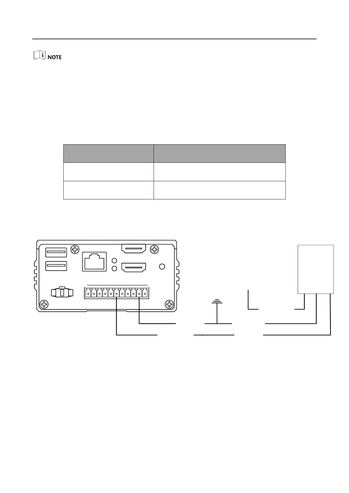
The vision box adopts NPN opto-isolated output, so different connection modes need to be
adopted according to the electrical features of different connected devices when they send signal.
PNP External Device
PNP
Device
Power Supply
Signal Line
Power Supply
Ground
VCC
Opto-Isolated
Output
GND of VCC
USB2.0 LAN
PWR
HDD
HDMI1
HDMI2
1 2 3 4 G 1 2 3 4 C G
DI
DO
LIGHT
1 2 3 4 G 1 2 3 4 C G
Output Common
Ground
Figure 3-4 Output Signal Connects PNP Device
NPN External Device

Questions and Answers:

Question and Answer IconNeed help?

Do you have a question about the HikRobot VB2200 Series and is the answer not in the manual?

HikRobot VB2200 Series Specifications

General IconGeneral
BrandHikRobot
ModelVB2200 Series
CategoryController
LanguageEnglish

Related product manuals