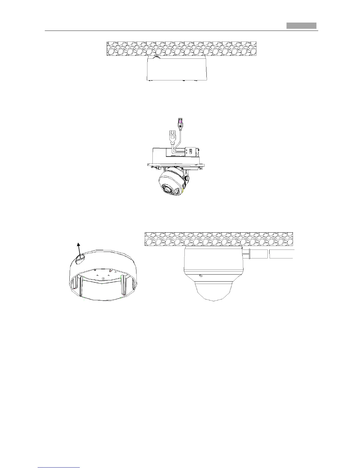
Figure 3-32 Mount the Camera
Note: If you need to pull the cable through the cable outlet from the side of the camera, please
remove the cover and use water-proof joints and water-proof pipe to route the cables.
Figure 3-33 Route Cable through Side Outlet
5. After connecting the network cable and power cable, view the image of the camera over the
network. Loosen the lock screws; adjust the panning position and tilting position and rotate the
lens to get the desired surveillance angle; fasten the lock screws.
 Loading...