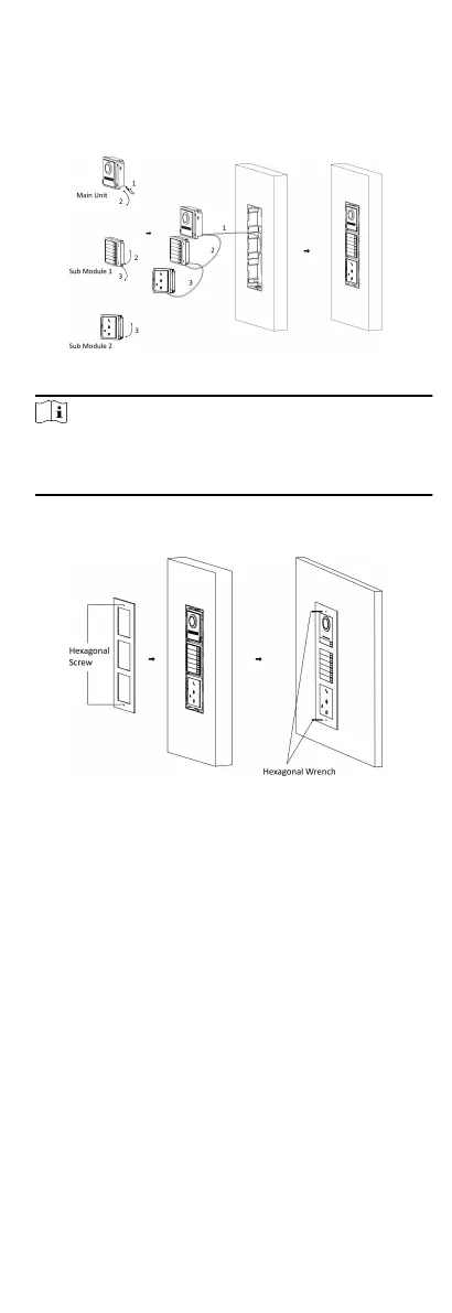
2) Connect the other end of Cable 2 to the input interface of
Sub Module 1. Connect one end of Cable 3 to the output
interface of Sub Module 1 and insert it into the middle grid.
3) Connect the other end of Cable 3 to the input interface of
Sub Module 2. Insert it into the
boom grid.
Figure 4-29 Connect Cables and Insert Modules
Note
Cable 1 refers to the cables pulled out from the wall that
connected to the main unit. Cable 2 and Cable 3 refer to the
module-connecng line in the accessory package.
8. Fix the cover and the main unit with 2 socket head cap screws
by using a hexagon wrench (supplied).
Figure 4-30 Fix the Cover
4.4 More-Than-Three Module Installaon
The PMR module can be used in the four-module or six-module
combinaon and here takes six-module installaon as example.
4.4.1 More-than-Three Module Surface
Mounng
25
 Loading...