4.1 Control Box Assembly
Chapter 4: Removal, Replacement, and Adjustment Procedures
Page 4 - 4 Hill-Rom® Basic Care™ Bed, Hill-Rom® 305 Manual Bed,
Hill-Rom® 405 Electric Bed Service Manual (MAN336 REV 2)
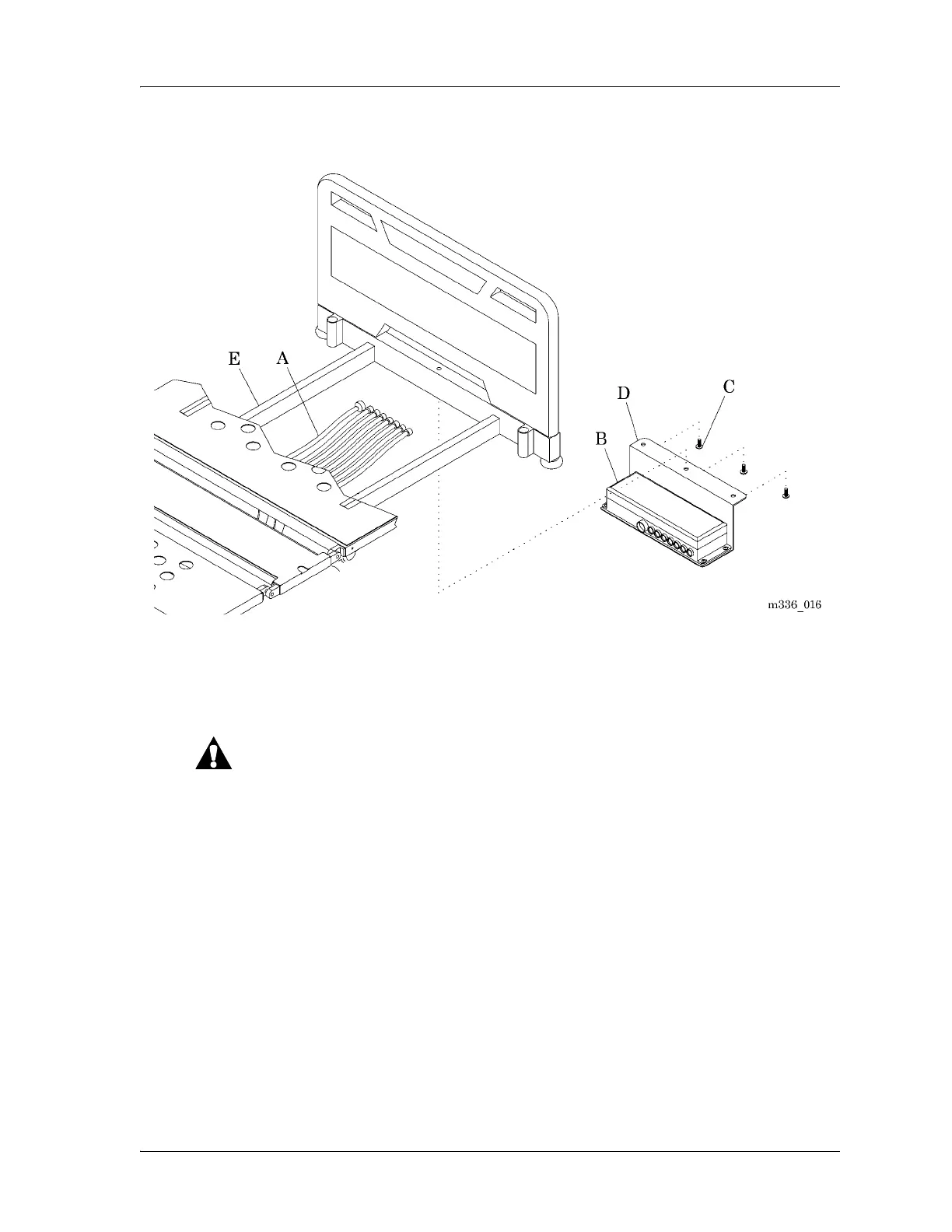
Figure 4-1. Control Box Assembly
Replacement
1. Do the removal procedure in the reverse order.
Connect the cables to the correct socket. Failure to do so may cause
the equipment to operate incorrectly.
2. Make sure the numbers marked on the cables (A) match the numbers
marked on the control box assembly (B).
3. Do the “Function Checks” on page 2-2.