4.11 Hilow Motor
Chapter 4: Removal, Replacement, and Adjustment Procedures
Page 4 - 26 Hill-Rom® Basic Care™ Bed, Hill-Rom® 305 Manual Bed,
Hill-Rom® 405 Electric Bed Service Manual (MAN336 REV 2)
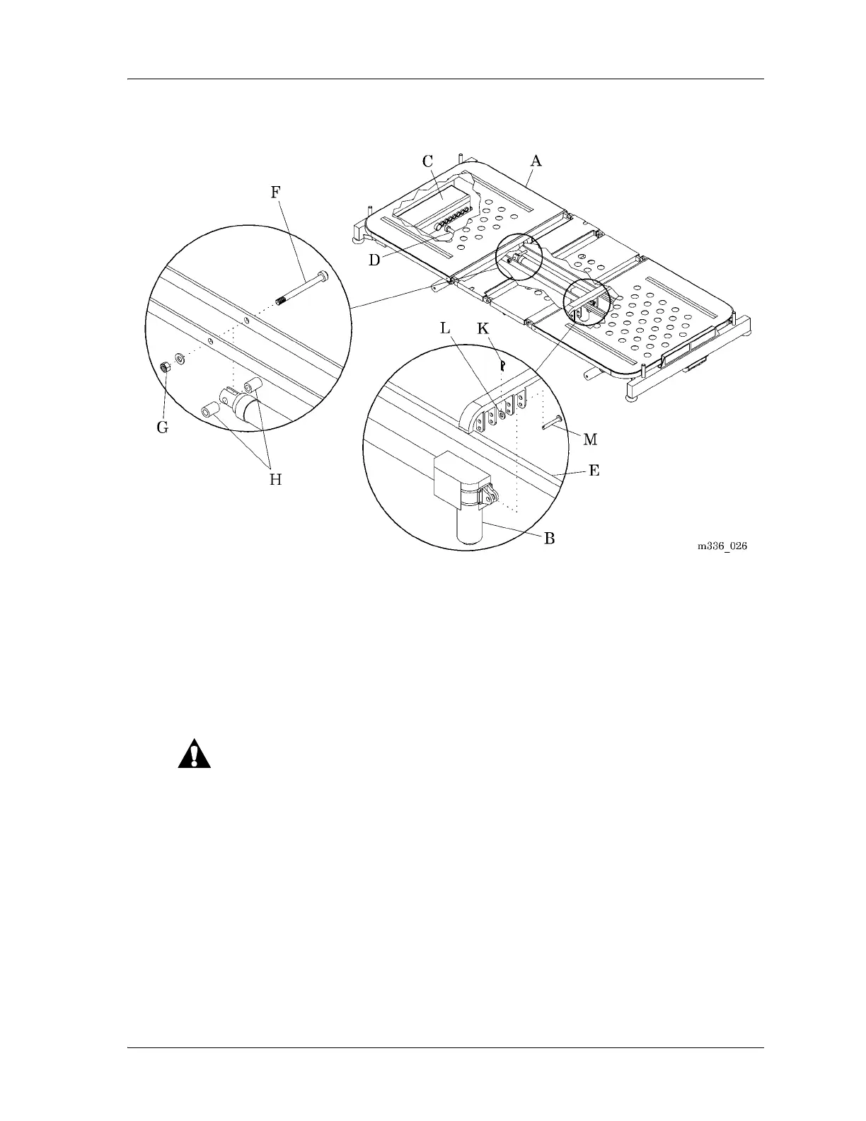
Figure 4-11. Hilow Motor
8. Remove the bolt (F), nut (G), and two spacers (H) that attach half of the
hilow motor (B) to the bed frame (E).
9. Remove the retaining ring (K), washer (L), and pin (M) that attach the
other half of the hilow motor (B) to the bed frame (E).
Replacement
Keep enough slack in the cables to allow the bed to move through its
full range of motion. Make sure the bed cables do not bind and do not
have any force applied to them. Failure to do so could cause equipment
damage.
1. When you route the cables, make sure they have enough slack for the bed
to move through its full range of motion.
2. Do the removal procedure in the reverse order.
3. Do the “Function Checks” on page 2-2.