2.9 Bed Connected to AC Power, Brakes Not Applied Detection Malfunction
Chapter 2: Troubleshooting Procedures
CareAssist® and CareAssist® ES Bed Service Manual (MAN330 REV 4) Page 2 - 25
2
b. Disconnect the foot column extension cable in the central rail of the
bed frame.
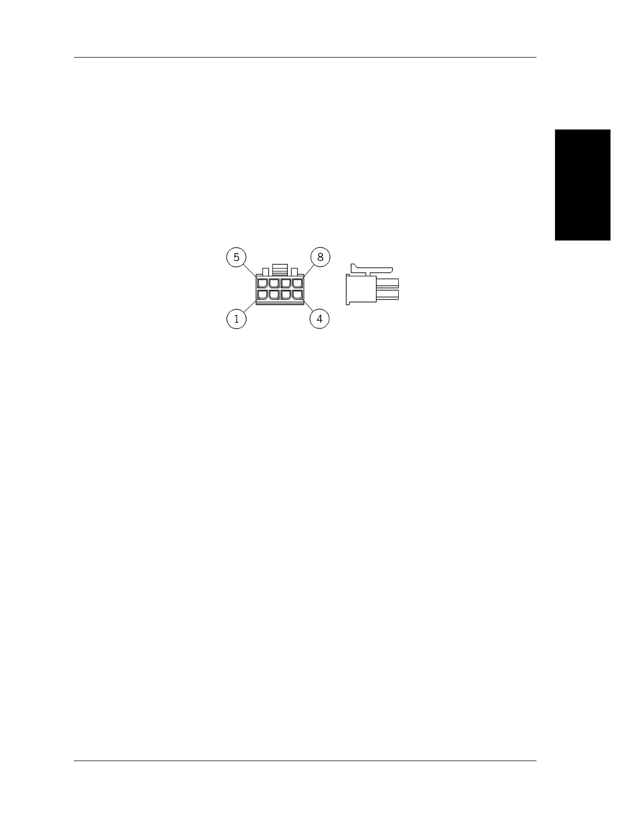
c. The same verification applies to the terminals of the 8-pin connector in
the central rail of the bed frame by checking the operation of the brake
detection switch from terminals 1 and 6 of the foot column (see figure
2-2 on page 2-25).
Figure 2-2. 8-pin connector
The foot column cable connections and brake detection switch continuity
are correct.
Yes No
↓→Replace the foot column (refer to procedure 4.10 on page 4-34)
(A model beds) or (refer to procedure 4.22 on page 4-68) (B
model and newer beds), then go to “Final Actions” on page 2-12.
6. Do the following to make sure the foot column extension operates
correctly.
a. Remove the power supply cover.
b. Disconnect connector #3 (8-pin blue) on the power board.
c. The same verification applies to the terminals of connector #3 (8-pin
blue) at the level of the power supply (A model beds) or connector #4
(8-pin yellow) of the motor control P.C. board (B model and newer
beds) at the level of the bed by checking the operation of the brake
detection switch from terminals 1 and 6 (see figure 2-2 on page 2-25)
of the foot column extension cable.
The extension cable (A model beds), column cable connections, and switch
continuity are correct.
Yes No
↓→Replace the foot hilow column and extension cable subassembly
(refer to procedure 4.10 on page 4-34) (A model beds) or (refer

 Loading...