4.1 Manual Hilow Drive Assembly
Chapter 4: Removal, Replacement, and Adjustment Procedures
Resident
TM
LTC Bed Service Manual (man136rc) Page 4 - 7
4
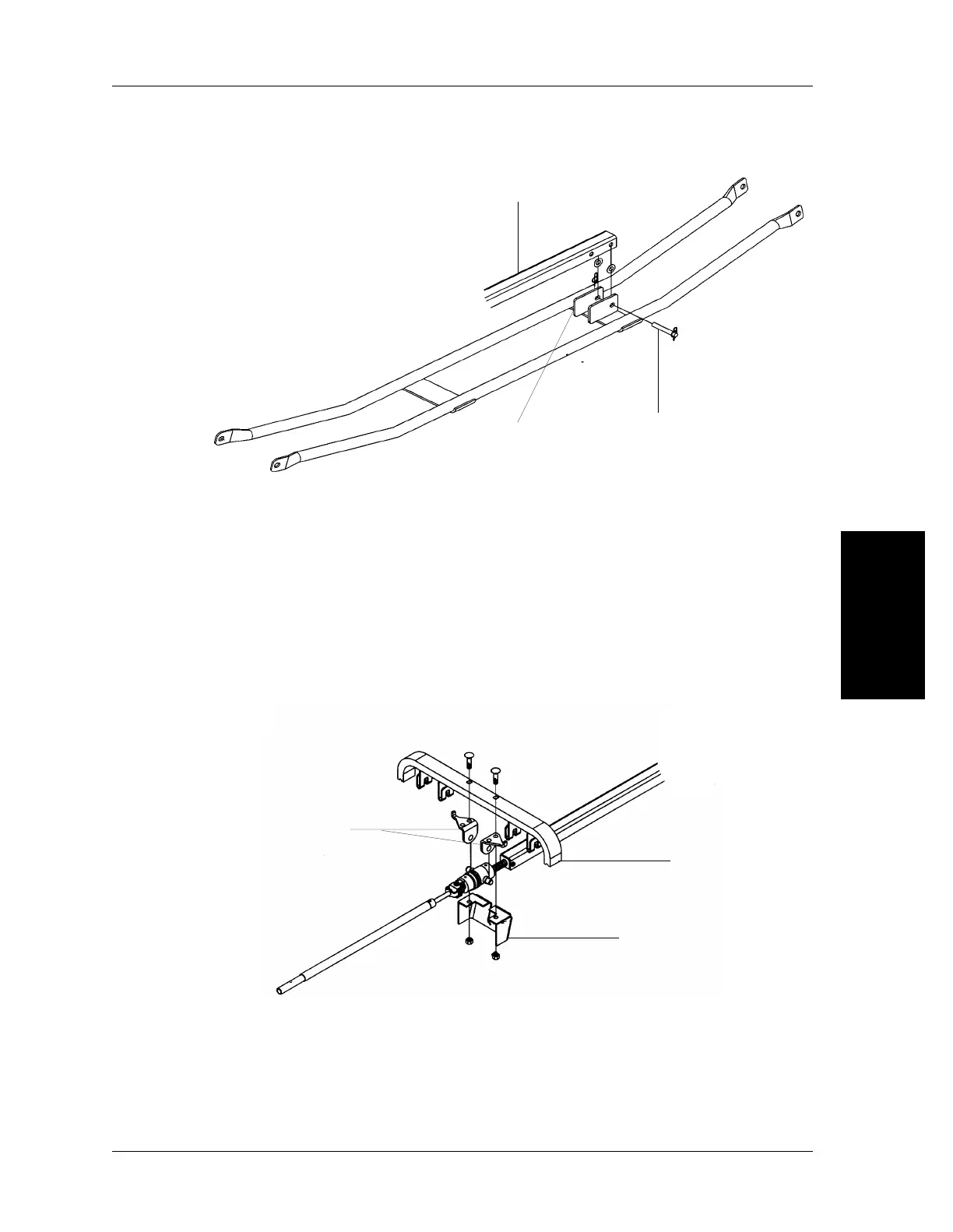
Figure 4-4. Removal of the Hilow Screw Assembly from the Pivot Connector Weldment
8. Raise the foot section assembly, and fold it over toward the thigh section
assembly to gain access to the hilow support brackets.
9. Use the socket wrench with a 9/16" deep-well socket to remove the nuts
and carriage bolts securing the hilow support bracket (A) and the two
mounting brackets (C) to the hilow support cross beam (B) (see figure 4-5
on page 4-7). Remove the hilow drive assembly.
Figure 4-5. Removal of the Hilow Drive Assembly from the Frame Assembly
Replacement
1. Using light oil, lubricate the hilow screw assembly threads.
A
B
C
m136_121
A
B
m136_113
C
 Loading...