EasyManua.ls Logo

Hillstone SG-6000-E2800 - Figure 1-22: SG-6000-E1100 (WLAN+4 G Version) Back Panel; LED Indicators; Table 1-18: Back Panel Description of SG-6000-E1100 (WLAN+4 G Version); Table 1-19: Front Panel LED Descriptions

Default Icon
68 pages
Print Icon
To Next Page IconTo Next Page
To Previous Page IconTo Previous Page
Loading...
13
Chapter 1 Introduction | Hillstone
Hillstone SG-6000 E-Series Hardware Reference Guide
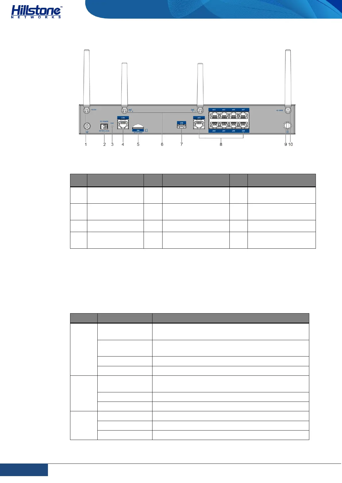
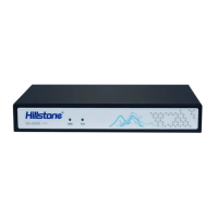
Figure 1-22: SG-6000-E1100 (WLAN+4G version) Back Panel
Table 1-18: Back Panel Description of SG-6000-E1100 (WLAN+4G version)
No.
Label
No.
Label
No.
Label
1
SMA connector
for 4G antenna
5
SIM: SIM card slot
9
Security keyhole
2
DC POWER: DC
power interface
6
SMA connectors for
WLAN antennas
10
SMA connector for
4G antenna
3
CLR: CLR button
7
USB: USB port
-
-
4
CON: Console
port
8
e0/0 - e0/8: Gigabit
Ethernet port
-
-
LED Indicators
The following table describes the meanings of LED indicators on the front panels of
Hillstone devices.
Table 1-19: Front Panel LED Descriptions
LED
Color/Status
Description
PWR
Green/Always
on
The device power is running normally.
Orange/Always
on
The device power is running abnormally.
Red/Always on
Power failure so the system is down.
Off
The device is powered off.
STA
Green/Always
on
The system is booting.
Green/Blinking
The system is running normally.
Red/Always on
The system has failed to boot or has an error.
ALM
Red/Always on
The system is sending alarm(s).
Green/Blinking
The system is waiting.
Orange/Blinking
The system is using a trial license.

Table of Contents

Related product manuals