List of Figures | Hillstone
Hillstone SG-6000 E-Series Hardware Reference Guide
List of Figures
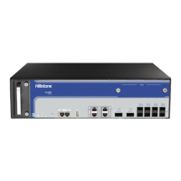
Figure 1-1:SG-6000-E6360 Front Panel .................................................................... 1
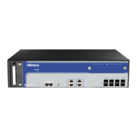
Figure 1-2: SG-6000-E6160 Front Panel ..................................................................... 2
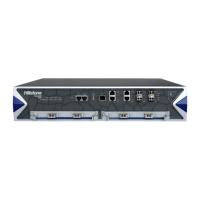
Figure 1-3:SG-6000-E5960 Front Panel .................................................................... 3
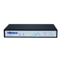
Figure 1-4: SG-6000-E5560 Front Panel ..................................................................... 3
Figure 1-5: Front Panel of SG-6000-E3960 ................................................................. 4
Figure 1-6: Front Panel of SG-6000-E3662 ................................................................. 5
Figure 1-7: Front Panel of SG-6000-E2800 ................................................................. 6
Figure 1-8: SG-6000-E1700 Front Panel ..................................................................... 6
Figure 1-9: SG-6000-E1600 Front Panel ..................................................................... 7
Figure 1-10: Front Panel of SG-6000-E1100 (WLAN version) ......................................... 7
Figure 1-12: Front Panel of SG-6000-E1100 (4G version) ............................................. 8
Figure 1-13: Front Panel of SG-6000-E1100 (WLAN+4G version) ................................... 8
Figure 1-14: SG-6000-E6360 Back Panel ................................................................... 9
Figure 1-15: SG-6000-E5960 Back Panel ................................................................. 10
Figure 1-16: SG-6000-E5560 Back Panel ................................................................. 10
Figure 1-17: Back Panel of SG-6000-E3960 .............................................................. 10
Figure 1-18: SG-6000-E1600 Back Panel ................................................................. 10
Figure 1-19: SG-6000-E1100 (WLAN version) Back Panel ........................................... 11
Figure 1-21: SG-6000-E1100 (4G version) Back Panel ............................................... 12
Figure 1-23: AC Power Module ................................................................................ 29
Figure 1-24: DC Power Module ............................................................................... 29
Figure 3-1: Installing the Rubber Pads ..................................................................... 35
Figure 3-2: Installing the Floating Nuts .................................................................... 36
Figure 3-3: Installing the Rack-mounting Ears (1U Chassis as example) ....................... 37
Figure 3-4: Installing the Device in a Rack (1U Chassis as example) ............................ 37
Figure 3-5: Connecting the Ground Wire (1U Chassis as example) ............................... 38
Figure 3-6: Connecting the Ethernet Copper Cable .................................................... 39
Figure 3-7: Connecting the Ethernet Fiber Cable ....................................................... 40
Figure 3-8: Connecting an AC Power Cable ............................................................... 41
Figure 3-9: Connecting a DC Power Cable ................................................................ 42
Figure 3-10: 3 WLAN and 4G Antennas .................................................................... 42
Figure 4-1: Console Port Configuration .................................................................... 44
Figure 4-2: Setting Parameters for the Terminal Session ............................................ 45
Figure 5-1: Installing Power Supply Module .............................................................. 47
Figure 5-2: Pulling Anti-dust Mesh Out ..................................................................... 49
Figure 5-3: Removing the Blank Panel ..................................................................... 50
Figure 5-4: Placing the Hard Disk Module ................................................................. 51
Figure 5-5: Fixing the Hard Disk Module ................................................................... 51
Figure 5-6: Installing the Blank Panel ...................................................................... 52