EasyManuals Logo
Home>HIMA>Control Unit>HIMax X-COM 01 E

HIMA HIMax X-COM 01 E User Manual

HIMA HIMax X-COM 01 E
46 pages
To Next Page IconTo Next Page
To Previous Page IconTo Previous Page
Page #12 background imageLoading...
Page #12 background image
3 Product Description XCOM 01 E
Page 12 of 46 HI 801 566 E Rev. 13.00.00
3.5 Structure
Essential functional units of the module are:
Processor system
Ethernet switch
Ethernet interface
Fieldbus submodule
Indicators, see Chapter 3.5.8.
For details on the associated connector boards, see also Chapter 3.7.1 and
Chapter 3.7.2.
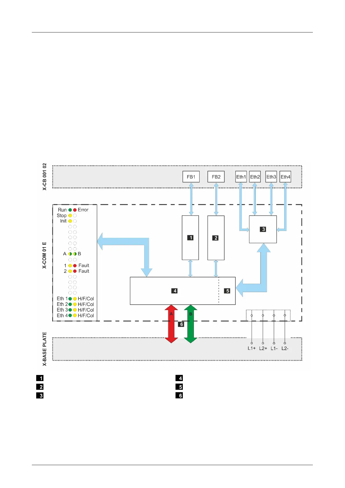
3.5.1 Block Diagram with X-CB 001 02 Connector Board
The following block diagram illustrates the structure of the module with the X-CB 001 02
Connector Board:
Fieldbus submodule 1
Fieldbus submodule 2
Ethernet switch
Processor system
Ethernet interface
System buses
Figure 2: Block Diagram with X-CB 001 02 Connector Board

Table of Contents

Questions and Answers:

Question and Answer IconNeed help?

Do you have a question about the HIMA HIMax X-COM 01 E and is the answer not in the manual?

HIMA HIMax X-COM 01 E Specifications

General IconGeneral
BrandHIMA
ModelHIMax X-COM 01 E
CategoryControl Unit
LanguageEnglish

Related product manuals