EasyManuals Logo
Home>HIMA>Control Unit>HIMax X-COM 01 E

HIMA HIMax X-COM 01 E User Manual

HIMA HIMax X-COM 01 E
46 pages
To Next Page IconTo Next Page
To Previous Page IconTo Previous Page
Page #22 background imageLoading...
Page #22 background image
3 Product Description X‑COM 01 E
Page 22 of 46 HI 801 566 E Rev. 13.00.00
3.7 Connector Board
The connector board forms a functional unit with the module and connects the module to other
systems via the Ethernet and fieldbus interfaces. The connector board must be inserted into the
appropriate slot prior to mounting the module on the base plate.
Two connector boards with various connection sockets are available for this module. The
connection sockets are described in the following chapters.
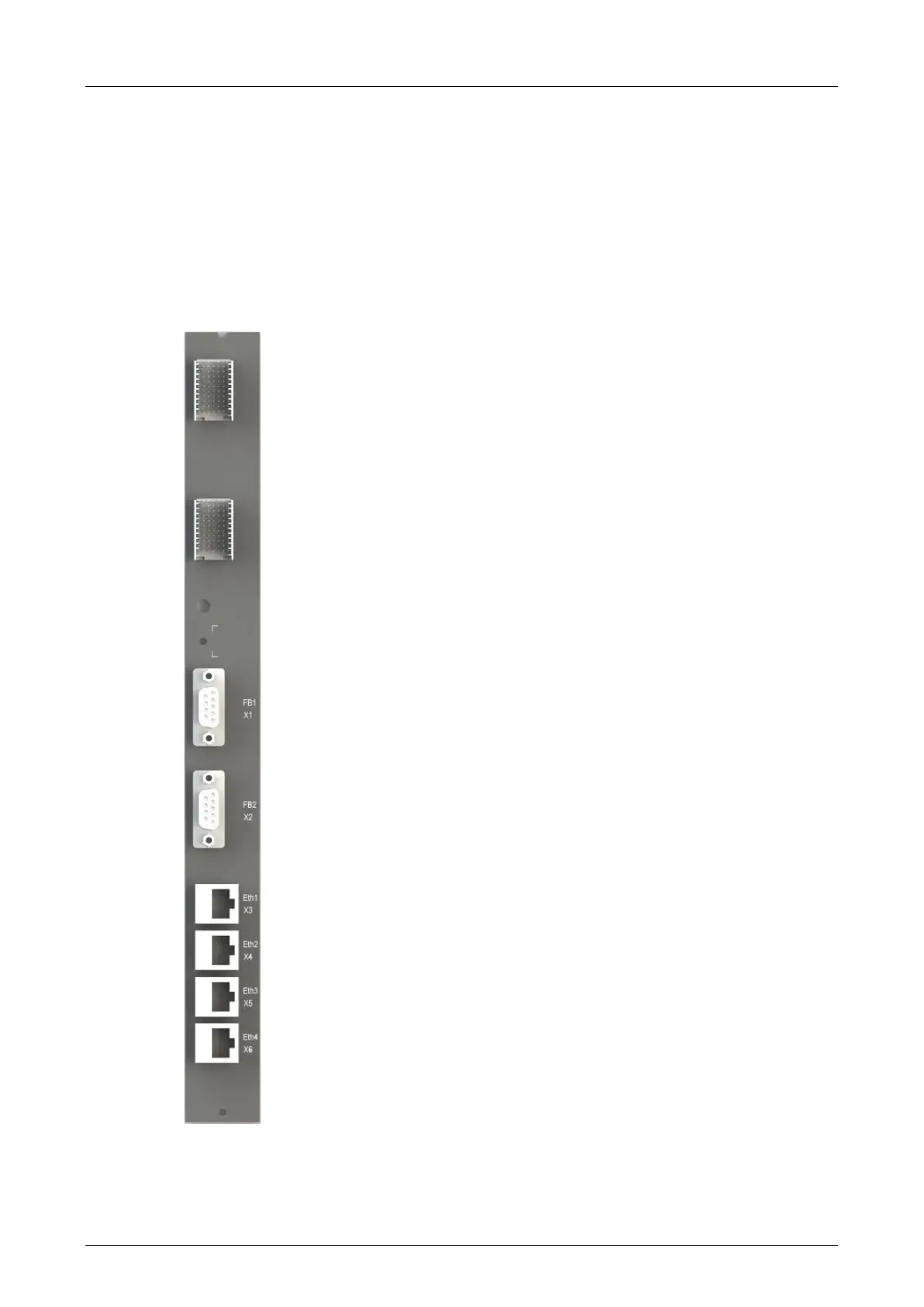
3.7.1 Ports on the X-CB 001 02 Connector Board
The designations for the connector socket are printed on the connector board.
Figure 6: X-CB 001 02 Connector Board

Table of Contents

Questions and Answers:

Question and Answer IconNeed help?

Do you have a question about the HIMA HIMax X-COM 01 E and is the answer not in the manual?

HIMA HIMax X-COM 01 E Specifications

General IconGeneral
BrandHIMA
ModelHIMax X-COM 01 E
CategoryControl Unit
LanguageEnglish

Related product manuals