X‑COM 01 E 3 Product Description
HI 801 566 E Rev. 13.00.00 Page 17 of 46
The LEDs indicate the operating state of the module. All LEDs should be considered together.
The LEDs on the module are divided into the following groups:
▪ Module status indicators (Run, Error, Stop, Init)
▪ System bus indicators (A, B)
▪ Fieldbus and automation network indicators (1, 2, Fault)
▪ Communication indicators (Ethernet)
After connecting the supply voltage, an LED test is performed and all the LEDs are lit for at least
2 s. The color of two-color LEDs changes once during the test.
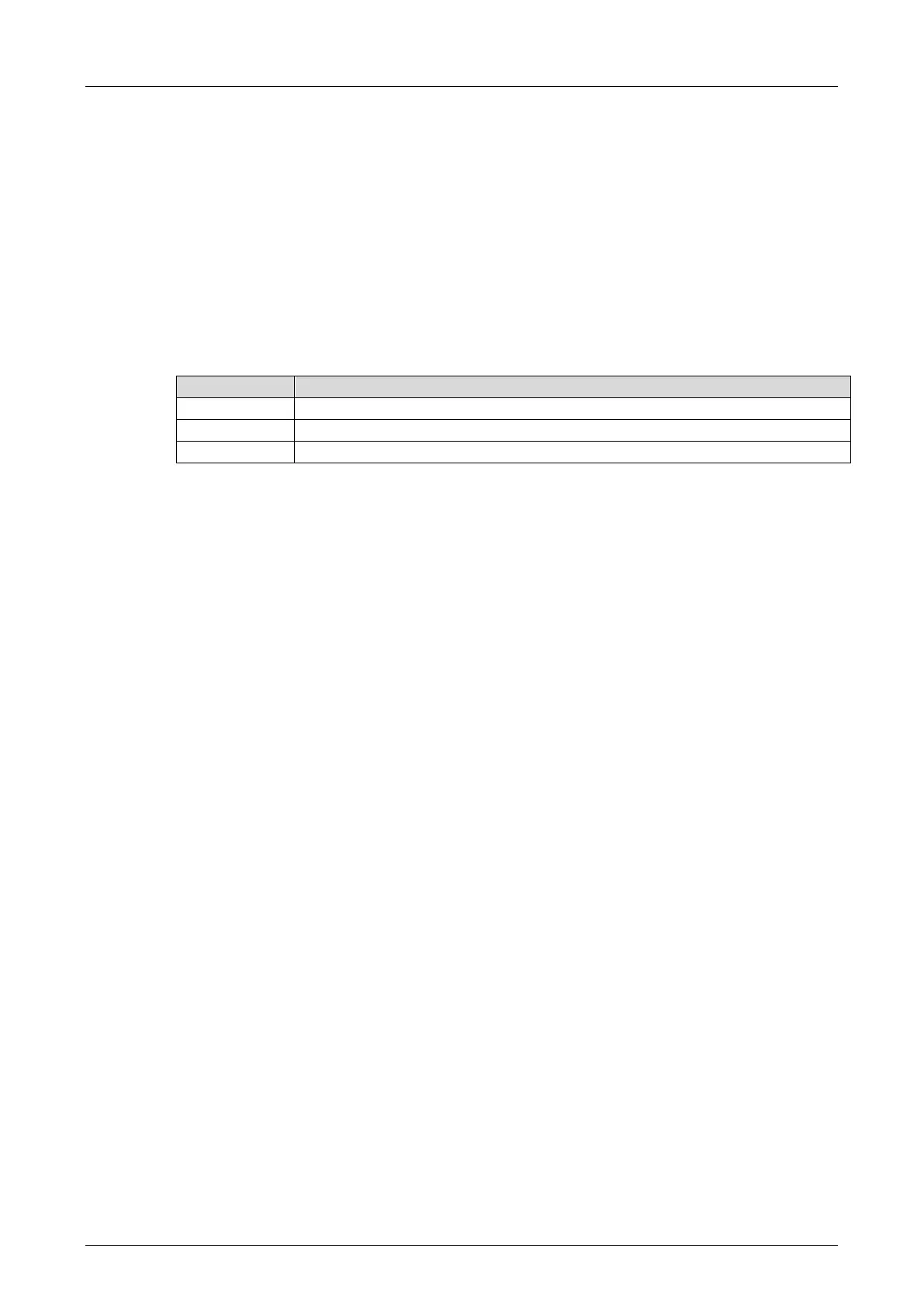
Definition of blinking frequencies
The following table defines the blinking frequencies:
Short (200 ms) on, short (200 ms) off, short (200 ms) on, long (600 ms) off.
Table 6: Blinking Frequencies of the LEDs
Some LEDs can report warnings (On) and faults or errors (Blinking1), see the following tables.
The indication of errors or faults has priority over the indication of warnings. Warnings cannot be
reported if errors or faults are being signaled.