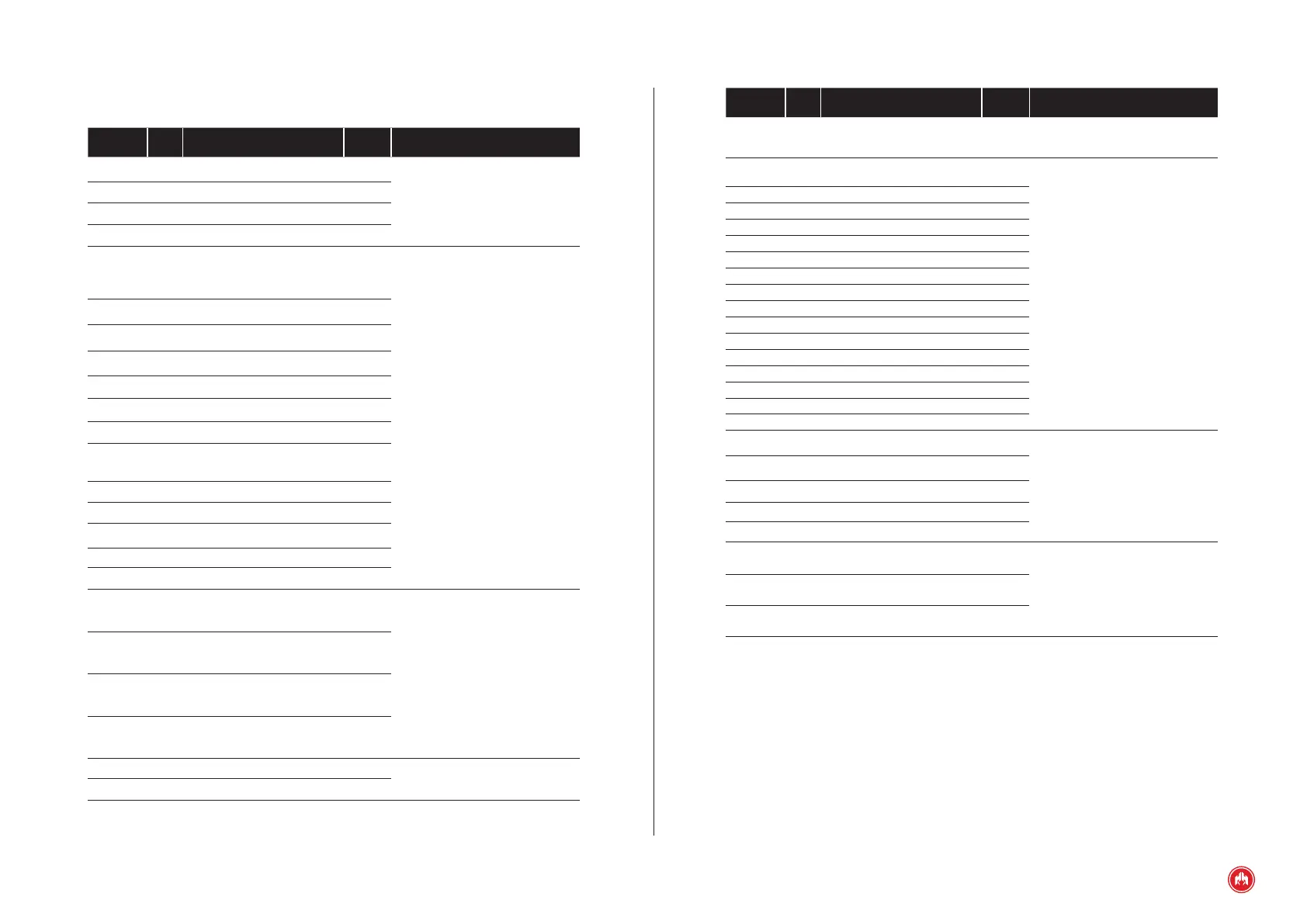
(APPENDIX I) PARAMETERS TABLE | PAGE 66
Parameter PSW Description Default value Range
139 2 Filter alarm probe 3 5’ 0”…255”
140 2 Mode alarm probe 3 0 0..2
141 2
Management alarm probe 4
Temperature probe 4
(from version PHG7 v419)
0 0..4
142 2 Filter alarm probe 4 5’ 0”…255”
143 2 Mode alarm probe 4 0 0..2
144 2
Management alarm J1939
Communication engine
(only expansion PHG7J)
4 0..4
145 2 Filter alarm J1939 1’ 0”…255”
146 2 Mode alarm J1939 0 0..2
147 2
Management alarm probe 1 level 2
Temperature probe 1 level 2
(from version PHG7 v420)
0 0..4
148 2
Filter alarm probe 1 level 2
5’ 0”…255”
149 2
Mode alarm probe 1 level 2
0 0..2
150 2
Management alarm probe 2 level 2
Temperature probe 2 level 2
(from version PHG7 v420)
0 0..4
151 2 Filter alarm probe 2 level 2 5’ 0”…255”
152 2 Mode alarm probe 2 level 2 0 0..2
153 2
Management alarm probe 3 level 2
Temperature probe 3 level 2
(from version PHG7 v420)
0 0..4
154 2 Filter alarm probe 3 level 2 5’ 0”…255”
155 2 Mode alarm probe 3 level 2 0 0..2
156 2
Management alarm probe 4 level 2
Temperature probe 4 level 2
(from version PHG7 v420)
0 0..4
157 2 Filter alarm probe 4 level 2 5’ 0”…255”
158 2 Mode alarm probe 4 level 2 0 0..2
180 2
Management alarm
IDMT
0 0..4
181 2 IDMT alarm lter 0 -
182 2 IDMT alarm mode 0 0..2
183
2
Management alarm probe 5
Temperature probe 5
(from version PHG7 v457)
0 0..4
Parameter PSW Description Default value Range
111 2
Management alarm extension 1
Programmable alarm 4 (from version
PHG6/7 v250)
0 0..4
112 2 Delay alarm extension 1 0’ 0”…255”
113 2 Mode alarm extension 1 0 0..2
114 2
Management alarm extension 2
Programmable alarm 5
(from version PHG6/7 v250)
0 0..4
115 2 Delay alarm extension 2 0’ 0”…255”
116 2 Mode alarm extension 2 0 0..2
117 2
Management alarm extension 3
Auxiliary battery alarm
(from version PHG6/7 v250)
0 0..4
118 2 Filter alarm extension 3 0’ 0”…255”
119 2 Mode alarm extension 3 0 0..2
120 2
Management alarm NFPA
High battery voltage
(from version PHG6 v300)
0 0..4
121 2 Filter alarm NFPA 1 0’ 0”…255”
122 2 Mode alarm NFPA 1 0 0..2
123 2
Management alarm extension 3
Low battery voltage when starting
(from version PHG6 v300)
0 0..4
124 2 Filter alarm NFPA 2 0’ 0”…255”
125 2 Mode alarm NFPA 2 0 0..2
129 2
Management alarm extension 4
Unit power
4 0..4
130 2 Filter alarm extension 4 5’ 0”…255”
131 2 Mode alarm extension 4 0 0..2
132 2
Management alarm probe 1
Temperature probe 1
(from version PHG7 v419)
0 0..4
133 2 Filter alarm probe 1 5’ 0”…255”
134 2 Mode alarm probe 1 0 0..2
135 2
Management alarm probe 2
Temperature probe 2
(from version PHG7 v419)
0 0..4
136 2 Filter alarm probe 2 5’ 0”…255”
137 2 Mode alarm probe 2 0 0..2
138 2
Management alarm probe 3
Temperature probe 3
(from version PHG7 v419)
0 0..4